Featured Articles
- Fall 2019 K&M Scholarship Winners
- Cast vs. Fabricated Machine Tool Structure Design Impact on Supply Chain Design
- How Large Is Large? Survey of Large CNC Machining In Michigan
- Large Machining of Large Bores – Machining, Measurement, Data Collection, Traceability and Data Retention
- Process Controls for Contract Manufacturers of Large Machining and Large Fabrications – Part One – Customer Supplier Interface
- Large CNC Machining Of Steel Casting – Custom Head for Tight Clearance Milling
- High Feed Milling Large Steel Castings – Don’t Let Casting Inclusions Disrupt Your Supply Chain
- Large CNC 3+2 Machining, Lean Manufacturing and the Seven Forms of Waste
- Large Fabrication Submerged Arc Welding (SAW)
- Large Machining of Weld Joint Surfaces for Large Fabrications
- Fall 2019 K&M Scholarship Winners
K & M Scholarship Recipient – Fall 2019
K & M Machine-Fabricating, Inc. in Cassopolis is proud to announce their Earl G. Marhanka Scholarship winners for the fall of 2019. This scholarship program was established in 2001 in recognition of K & M’s 50th anniversary and in honor of the entrepreneurial spirit of its founder, Mr. Earl G. Marhanka. To date, over $224,000 has been awarded to over 52 students of K & M employees. This year’s scholarship winners will receive $2,000. They are:
Skyler McKee – Skyler is a graduate of Cassopolis High School and will be attending Olivet College in Olivet, MI where he will be playing football for the Comets. Skyler plans on pursing business at Olivet and one day hopes to own his own construction business. Skyler is the son of Edward McKee, who works in the Burn Shop at K & M.
Caroline McLoughlin – Caroline is a graduate of Lake Michigan Catholic High School and will be attending Loyola University Chicago in the fall. Caroline plans on pursing a degree in business with a possible minor in dance. She hopes to one day help nonprofit startups. Caroline is the daughter of Derek McLoughlin, GM at K & M.
In addition to the 2 new recipients, 5 scholarship winners from previous years are eligible to renew their $2,000 scholarships. They are:
Continue reading →
• Maggie Baert (Butler University, by way of Penn High School) – daughter of Patrick Baert
• Zoe Laubach (Bethel College, by way of Edwardsburg High School) – daughter of William Green
• Jackson McLoughlin (Marquette University, by way of Lake Michigan Catholic High School) – son of Derek McLoughlin
• Madison McLoughlin (Loyola University New Orleans by way of Lake Michigan Catholic High School) – daughter of Derek McLoughlin
• Haily Shibinski (Southwestern Michigan College, by way of Brandywine High School) – daughter of Dave Shibinski. - Cast vs. Fabricated Machine Tool Structure Design Impact on Supply Chain Design
Spending on new metal working equipment in the US is projected to increase by $2.3 Billion in 2015 according to Gardner Research (1). How does the manufacturer of machine tools in the United States take advantage of this growth? This is an important question for machine tool design engineers and purchasing managers. The end user of a machine tool has many options that can meet her needs. In today’s competitive environment the end user considers the degree to which the machine tool meets her specific needs, the price and the lead time. To take advantage of the growth in capital spending machine tool builders must use machine design and supply change design to beat the competition. This article will explore the alternatives of cast versus fabricated structures in machine tool design and supply chain design.
Gardner Research’s 2015 Capital Spending Survey Machine Tools Executive Summary (1) reports that projected 2015 capital spending for US metalworking facilities will grow 37% compared to the latest estimate for 2014. Several industries are projected to have an increase from 2014 to 2015 of over 100%. These include metal cutting job shops, non-automotive forming and fabricating, industrial motors/hydraulic/mechanical components, custom processors, aerospace and plastic rubber products. If you are a builder of machine tools this is an opportunity you want to take advantage of.
The end user of machine tools wants performance, low price and short lead time. How does machine tool design impact these customer requirements? Machine tool design considerations for performance include damping, natural frequencies, inertial forces of moving members (Bamburg (2)), load bearing strength of components, stress when loaded, (AFS (3)), vibration control and heat control (Micromanufacturing (4)), and stiffness (Tobias and Koenigsberger (5)) to name a few. Design decisions will also impact:
- The degree of machine customization that can be offered
- The lead time to first production
- The lead time for production machines
- The fixed cost and variable cost structure of manufacturing the machine
- The cost to change design features at startup
- The cost to change design features over the life of the machine in the manufacturer’s portfolio
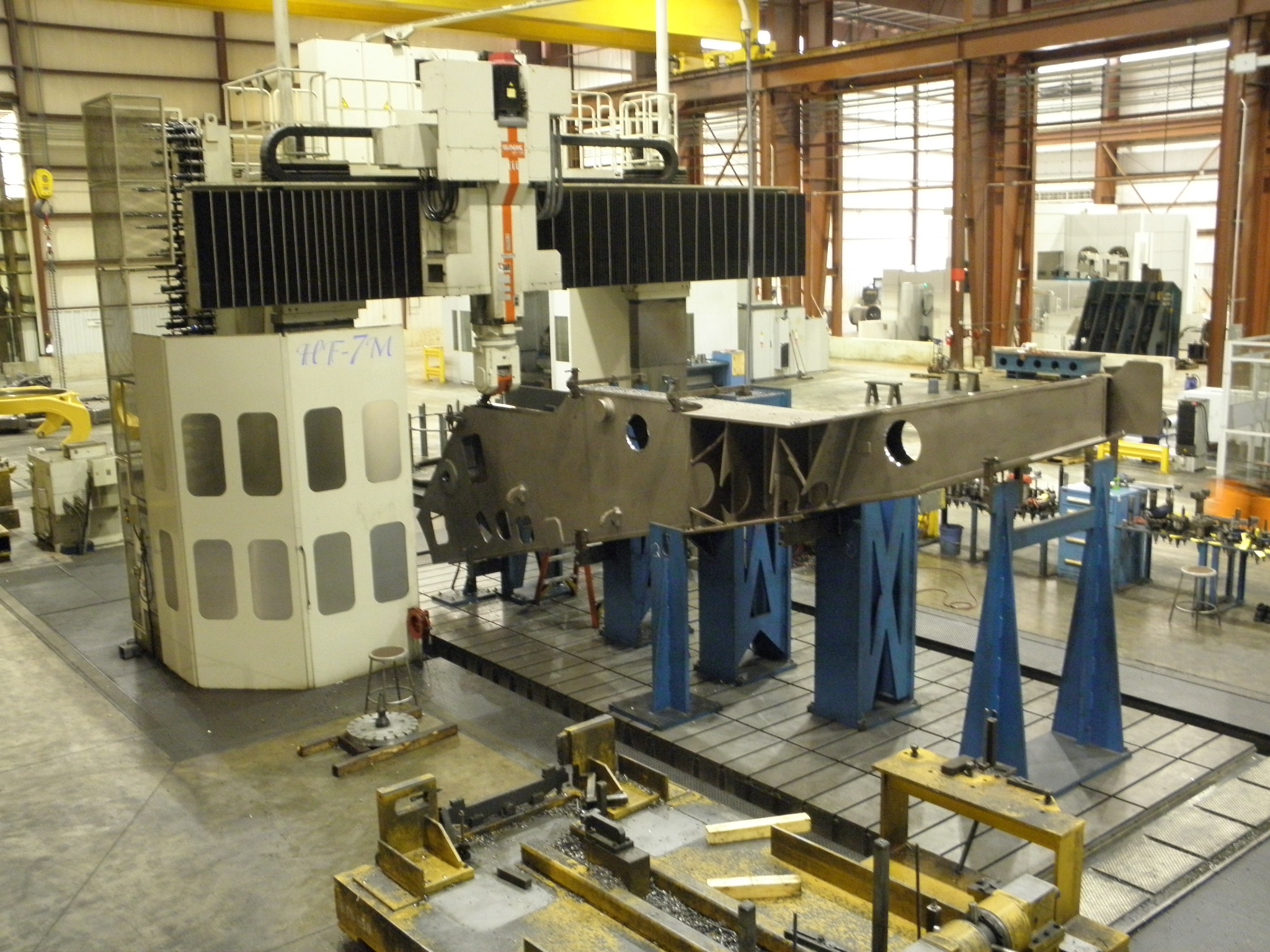
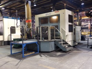
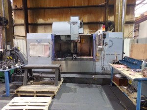
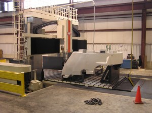
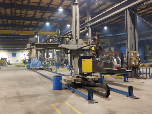
Performance of the machine tool is the primary consideration. Cast iron structures are able to handle high loads and high machining forces. Cast iron structures will transfer heat less effectively than fabricated structures, making them more stable under conditions of changing temperature. Cast iron dampens vibration better than steel. (Walker Machinery (6)). Picture #1 is a large CNC Vertical Gantry mill used for precision heavy machining of large components. The bed and column are cast iron. This is a large milling machine designed for heavy stock removal rates and machining precision.
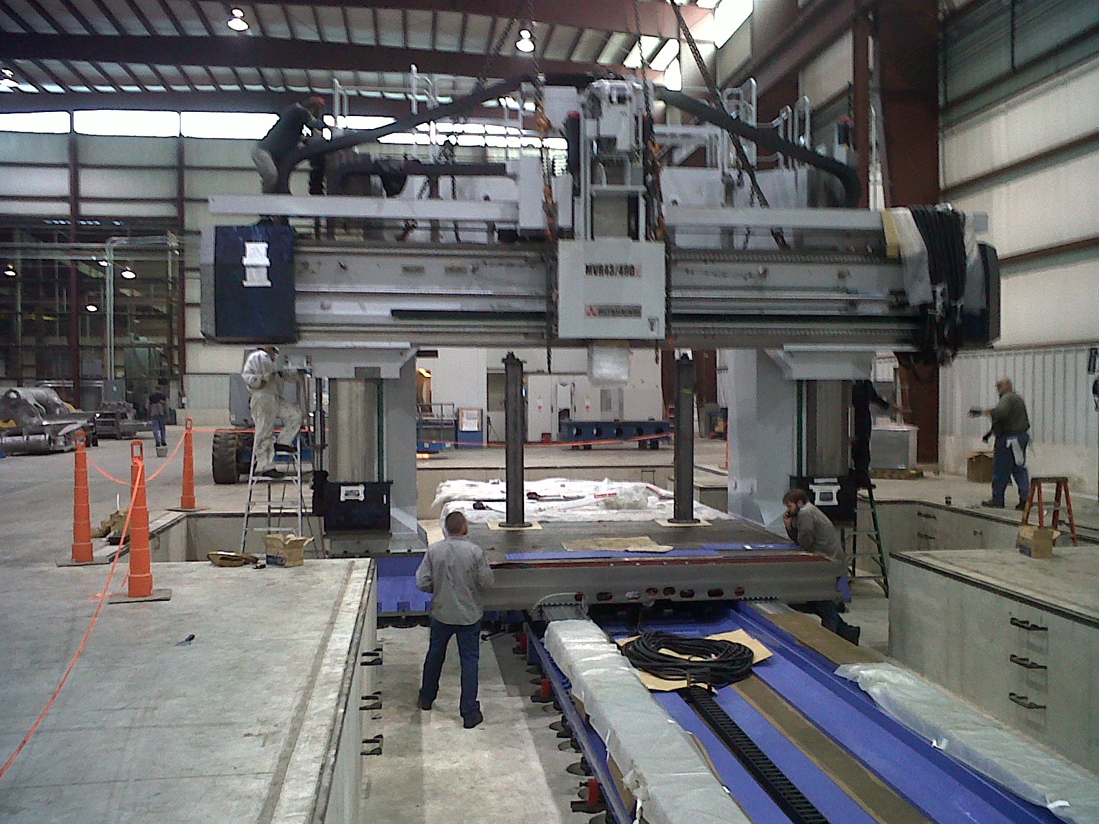
Picture 1 – Large Machine Tool Structure – Cast Iron
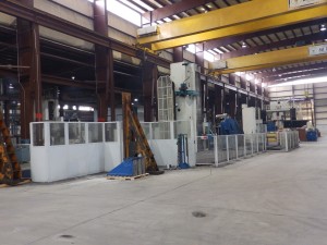
In many cases a well-designed steel fabrication can meet the performance characteristics of a cast iron structure. The design engineer has to determine if a cast base is required or if a fabricated structure can meet the performance requirements. Picture # 2 is a fabricated steel structure for a metal cutting machine. This machine is designed for lower metal removal rates, very low vibration at the tool tip, and high accuracy.
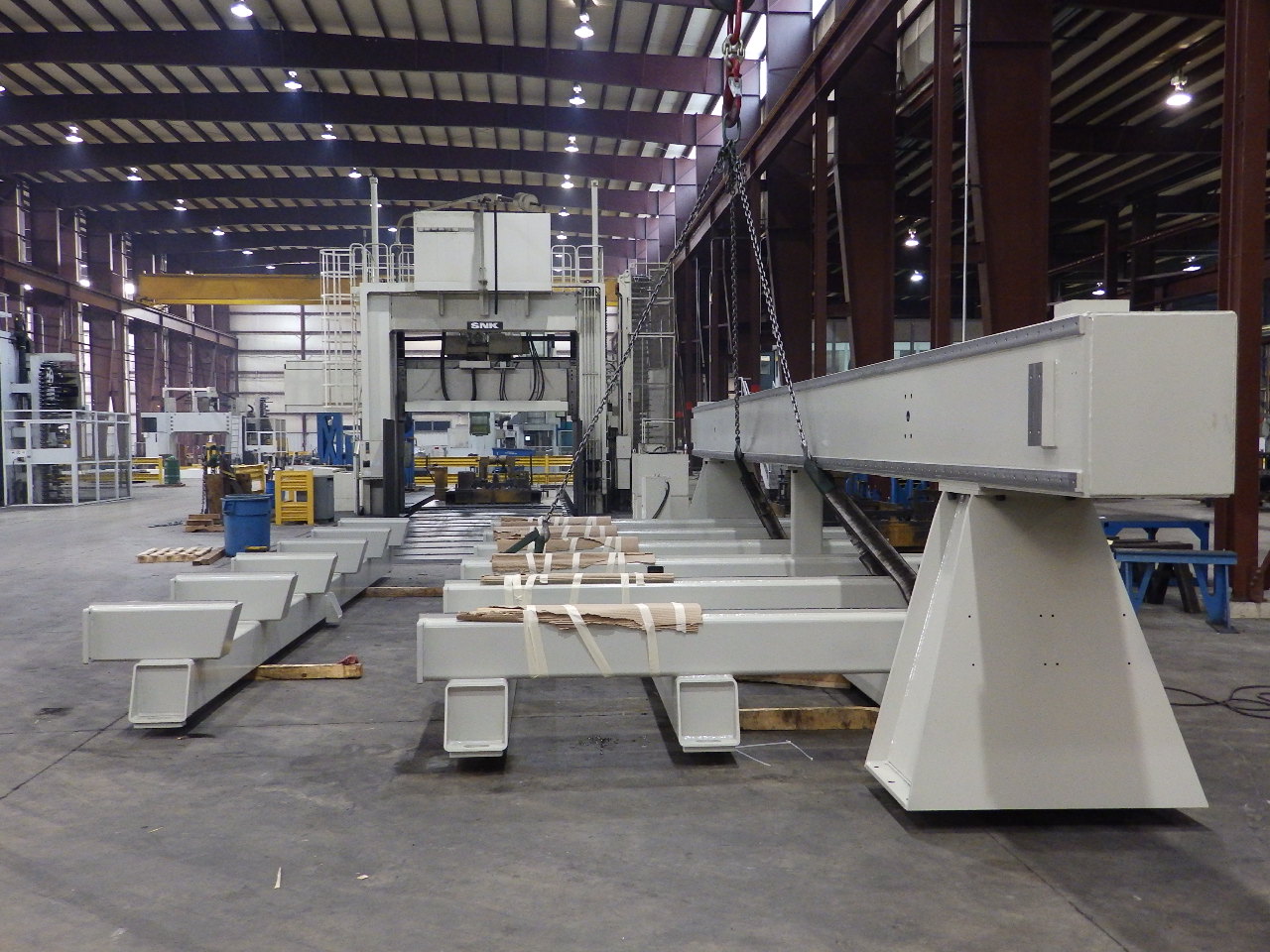
Picture 2 – Fabricated Machine Structure
How important is flexibility in machine design? Will offering customers the ability to customize each machine give the manufacturer a competitive advantage? Will the ability to incorporate new features and technology quickly help the manufacturer increase sales?
Cast iron components require a casting mold or pattern. Design, build and qualification of a casting mold or pattern takes time. If a change in design to the structure is required the mold or pattern must be modified or replaced. The requirement for a mold or pattern limits the flexibility for design changes. A structure that is fabricated from steel plate and steel tube requires little if any fixed tooling. Each structure that is designed can be unique.
Cost is an important consideration in the design of a machine tool structure. The casting mold or pattern is a fixed cost that must be incurred with cast structures. This fixed cost is not incurred with fabricated structures. The designer of a cast structure is able to put material in the structure only where it is needed. He has a great deal of design flexibility. He may be able to reduce the amount of material needed for the structure through casting design. (AFS (3)) There will be welding cost in a fabricated structure that is not present in a cast structure. The variable cost of the fabricated structure may be higher than the cast structure. It will depend on the design of each.
Lead times are an important consideration in design. The manufacturer that can deliver quickly often gets the order. The lead time to produce a cast structure is longer than the lead time to produce a fabricated structure. The casting has the lead time for the mold or pattern as well as the lead time to cast and machine the structure. Even after the mold or pattern is built, the lead time to pour a large casting may be longer that the lead time to obtain standard sizes of steel plate and tube and fabricate. The fabricated structure has the lead time advantage.
There are at least two types of design flexibility. One is the flexibility to modify a standard machine configuration for a specific customer. The other is to completely redesign a standard machine to incorporate the latest technology or machine features. Every machine can be different with a fabricated structure. The base design is modified to add or delete features. There is no or little fixed costs that will become obsolete if an entire standard machine design is discarded and a new design machine takes its place. Because a fabricated structure does not need a mold or pattern, the fabricated structure has the advantage in terms of design flexibility.
The structure design issues have been addressed above. Let’s take a look at design of the supply chain for a machine structure. There are three main processes in the manufacture of a cast structure. They are casting, machining and painting. There are four main processes in the manufacture of a fabricated structure. They are fabrication, stress relieving, machining, and painting. As the structure gets bigger the number of foundries that are able to cast the structure gets smaller. The capital investment in the facility to fabricate a large structure is smaller than the capital investment in the facility needed to cast a large structure. There are more companies that can fabricate a large structure than there are companies that can cast a large structure. The larger number of potential suppliers gives the machine tool company purchasing manager more options in looking for the right combination of price and delivery.
Transportation of the machine tool structure can be expensive. Large structures may require oversize load permits and their added cost. The ideal supply chain will have all of the processes performed by a single supplier. This will reduce transportation cost. If they cannot be completed by the same supplier having all the processes performed at facilities close to each other will minimize the transportation distance and cost between processes.
An indirect but real benefit of having one supplier responsible for all processes is the reduced supplier management costs incurred by the machine tool builder. The purchasing professional at the machine tool builder will have to manage only one supplier rather than several. There is also an increased accountability. With one supplier the machine tool builder and the supplier know who is responsible if there is a quality or delivery problem. With multiple suppliers there may be disagreement and time and money wasted finding the root cause of a problem and determining who is accountable for the costs to correct the problem.
Machine performance requirements may drive the machine tool builder to select a cast structure design. There are many advantages to a single source for fabricated steel machine tool structures. If the machine tool design permits a fabricated steel structure cost and lead time can be reduced. A single source for the complete fabricated structure can provide a high performing supply chain that is accountable for quality and delivery.
References:
- 2015 Capital Spending Survey Machine Tools Executive Summary
- Rapid Machine Design, Bamberg, Slocum,, Massachusetts Institute of Technology, Cambridge MA.
- Steel Fabrications vs. Castings, American Foundry Society (AFS), Schaumburg IL.
- Good vibration (control): Small vs. large machines, Kennedy, Micro manufacturing.
- Advances in Machine Tool Design and Research 1967, The University of Manchester Institute of Science and Technology, September 1967
- Walker Machinery
June 23, 2015
Continue reading → - How Large Is Large? Survey of Large CNC Machining In Michigan
Are you a buyer of large CNC machining capacity in the state of Michigan? Do you need to know the quantity and size of large CNC machines that are available for outsourcing in the state of Michigan? Research on the top companies in Michigan as ranked by a Google search for Large Machining Michigan and Large CNC Machining Michigan on February 10, 2015 was completed. The results are presented in this report.
Summary:
- Large is a relative term. Companies classified horizontal machines with a size capacity ranging from 0.7 cubic meters to 312 cubic meters of capacity as large.
- Only two companies in Michigan advertise large horizontal machines with over 60 cubic meters of capacity. Of the 6 machines that are advertised in Michigan over 60 cubic meters in capacity, 5 of the 6 are at one company.
- Only four companies in Michigan advertise large vertical machines with 80 cubic meters or larger capacity. Three of these companies have only one machine each in this size category. One company has 6 of the 10 machines that are advertised in this size category.
- The company that has the largest number of the largest size horizontal machines in Michigan is the same company that has the largest number of the largest size vertical machines in Michigan. This company is K&M Machine-Fabricating Inc., located in south-west Michigan.
Survey method:
A Google search on Large Machining Michigan and Large CNC Machining Michigan was done on February 10, 2015. The fourteen top ranked companies that offered large machining capacity and that listed the size and number of machines on their website were included in this survey. If the company website offered large machining or large CNC machining but did not list the machine sizes they were not included in the survey. If the company website listed only their largest machine they were included in the survey, but only as one machine of this size. This is not an all-encompassing survey of large machining in Michigan, but it is the best that could be done using information published on company websites. Companies that have large machining capacity but use this capacity for their own internal work were not included in the survey. This survey is focused on large machining capacity in the state of Michigan that is available for subcontract work.
The cubic meters of size capacity of each machine reported on a company website was calculated. Formula # 1 shows the formula that was used to calculate the size capacity of each machine in cubic meters. For purposes of this survey machines were placed into groups by size. The smallest machines are in the 10 cubic meter size capacity group. All machines described on a company website that had a size capacity less than or equal to 10 cubic meters were put into this group. The next size group is 20 cubic meters. All machines that have a capacity greater than 10 cubic meters but less than or equal to 20 cubic meters were put into the 20 cubic meter group. Size groups were incremented by 10 cubic meters.
Cubic Meters Capacity = (X axis travel meters) X ( Y axis travel meters) X (Z axis travel + W axis travel meters)
Formula #1 – Cubic Meters Machine CapacityThe survey breaks the available machines into two types; horizontal machines and vertical machines. The horizontal machine type includes horizontal machining centers, horizontal boring mills and horizontal jig mills. The vertical machine type includes vertical machining centers and vertical gantry mills.
Large Horizontal CNC Machines:
Thirteen companies in the survey reported a total of 87 large horizontal CNC machines on their websites. The machine size capacity ranged from a low 0.7 cubic meters to a high of 312 cubic meters. There is a wide range of what is considered large. Chart #1 is a histogram of the size capacity for the 87 large horizontal CNC machines reported by thirteen Michigan companies in the survey.
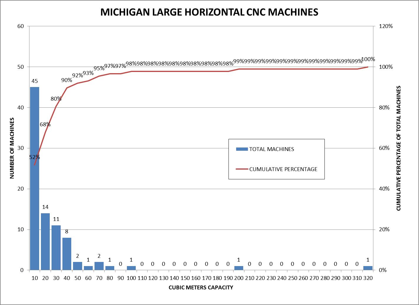
Chart #1 – Histogram of Large CNC Horizontal Machines
45 of the 87 large horizontal CNC machines in the survey, or 52%, have a size capacity of 10 cubic meters or less. 90 percent of the large horizontal CNCs in the survey have a size capacity of 40 cubic meters or less. Chart # 2 shows the distribution of large horizontal CNC machines in the survey by company. There are several companies that have machines on the smaller side of the large machine classification. Only two companies of the thirteen have machines with capacity of 60 cubic meters or larger. Of the two companies, one company has one machine with capacity of 60 cubic meters or larger. One company has 5 machines that range in capacity from 70 cubic meters to 320 cubic meters.
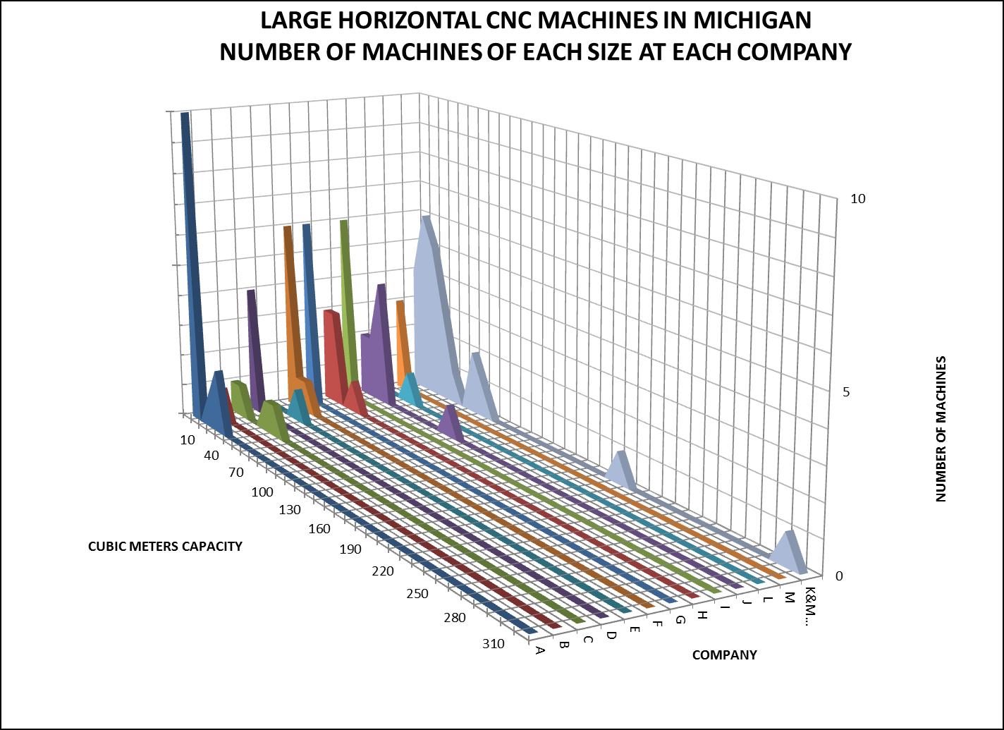
Chart #2 – Distribution of Large Horizontal Machines by Company
Picture # 1 shows a CNC horizontal machining center with a size capacity of 1.8 cubic meters. This machine is in the smallest size group in the survey, the 10 cubic meter machine size. Picture #2 shows a CNC horizontal boring machine with a size capacity of 312 cubic meters. This machine is in the largest size group in the survey, the 320 cubic meter size.
Picture #1 – 1.8 Cubic Meter Size Capacity Horizontal
Picture #2 – 312 Cubic Meter Size Capacity Horizontal
Large Vertical CNC Machines:
Fourteen companies in the survey reported a total of 71 large vertical CNC machines on their websites. The machine size capacity ranged from a low of 0.1 cubic meters to a high of 192 cubic meters. There is a wide range of what is considered large in the vertical CNC machine classification, just like in the horizontal machine classification. Chart # 3 is a histogram of the size capacity for the 71 large vertical CNC machines reported by fourteen Michigan companies in the survey.
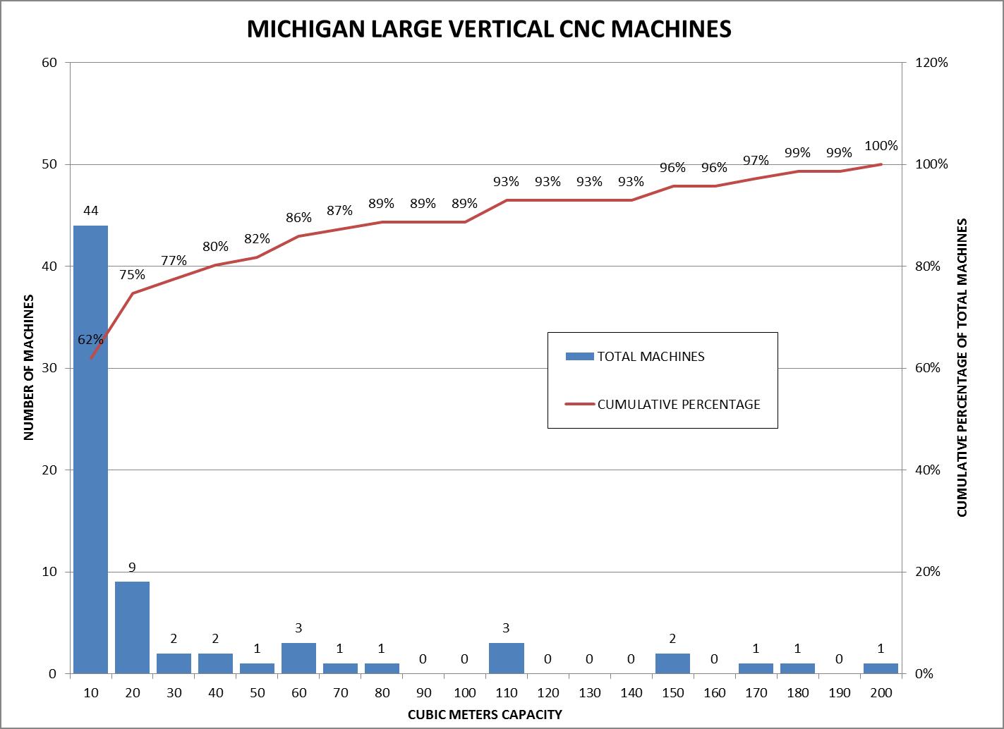
Chart #3 – Histogram of Large CNC Vertical Machines
44 of the 71 large vertical CNC machines in the survey, or 62%, have a size capacity of 10 cubic meters or less. 80 percent of the large vertical CNCs in the survey have a capacity of 40 cubic meters or less. Chart # 4 shows the distribution of large vertical CNC machines in the survey by company. There are several companies that have machines on the smaller side of the large machine classification. Only four companies of the fourteen have machines with capacity of 80 cubic meters or larger. Of the four companies, three companies have one machine each with over 80 cubic meters capacity. One company has 6 machines that range in size capacity from 110 cubic meters to 178 cubic meters.
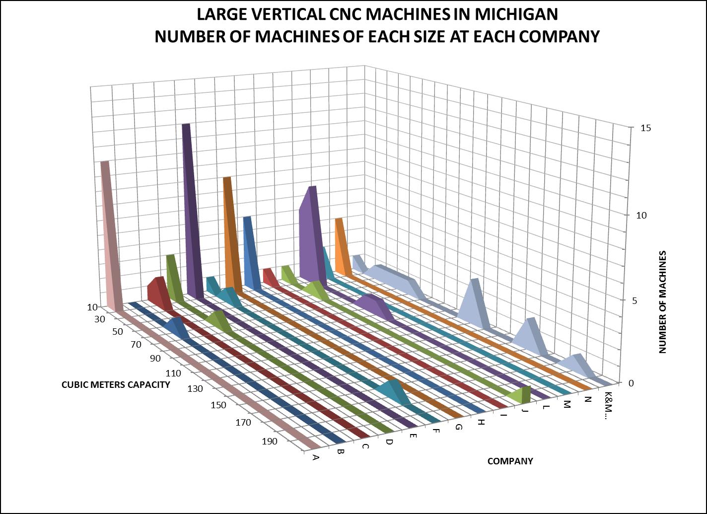
Chart #4 – Distribution of Large Vertical Machines by Company
Picture # 3 shows a CNC vertical machining center with a size capacity of 0.8 cubic meters. This machine is in the smallest size group in the survey, the 10 cubic meter machine size. Picture #4 shows a CNC vertical gantry machine with a size capacity of 178 cubic meters. This machine is in 180 cubic meter size group.
Picture #3 – 0.8 Cubic Meter Size Capacity Vertical

Picture #4 – 178 Cubic Meter Size Capacity Vertical
This survey shows that as the size of the machining to be outsourced increases, the number of available machines in Michigan is reduced and the number of companies that can handle the work is reduced as well. There is one company with multiple machines in the larger sizes of both the horizontal type and vertical type. This company has machines across the entire range of sizes that are considered large. This company is K&M Machine-Fabricating Inc. located in south-west Michigan.
A survey of large machining capacity across the United States will be conducted and reported in the near future.
February 23, 2015
Continue reading → - Large Machining of Large Bores – Machining, Measurement, Data Collection, Traceability and Data Retention
Large Fabrications and large castings often require machining of large bores. The large machining contract supplier must have machines, tools, gages, processes and data collection systems in place to machine close tolerance large bores to the customer’s requirement.
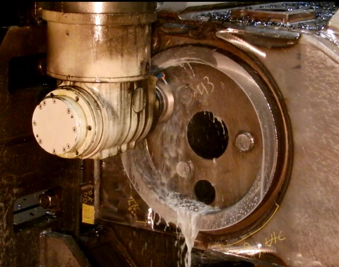
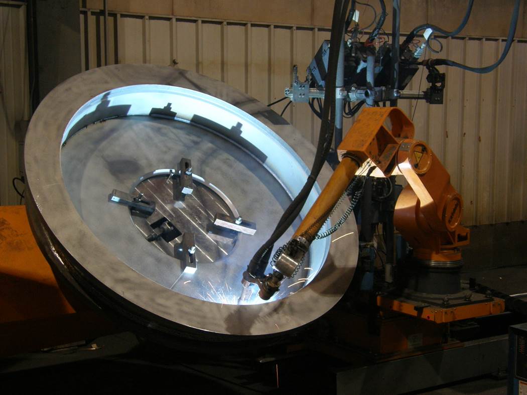
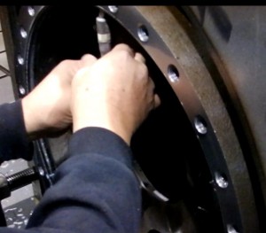
Large bores can be machined on a horizontal boring mill or on a vertical gantry mill. There is often a relatively large amount of stock removal on a large bore in a large casting or large fabrication. Compared to the location and diameter tolerances on the final machining operation the casting and fabrication location tolerances are large. A rough machining operation to reduce the amount of stock left for finish machining is required. Any operations that are required around the bore like face milling, drilling and tapping are performed before the finish bore operation. Any distortion of the part that will occur from these operations will occur before the finish bore is machined. These practices are common for all large machining suppliers. Picture # 1 shows rough machining of a 19.5 inch diameter bore with a milling cutter on a large vertical gantry machine. Picture # 2 shows drilling of bolt holes around the bore.

Picture #1 – Rough Machining the Bore

Picture #2 – Drilling Bolt Holes Around the Bore
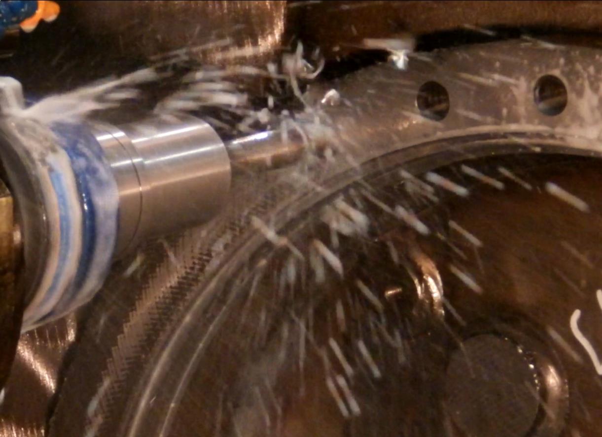
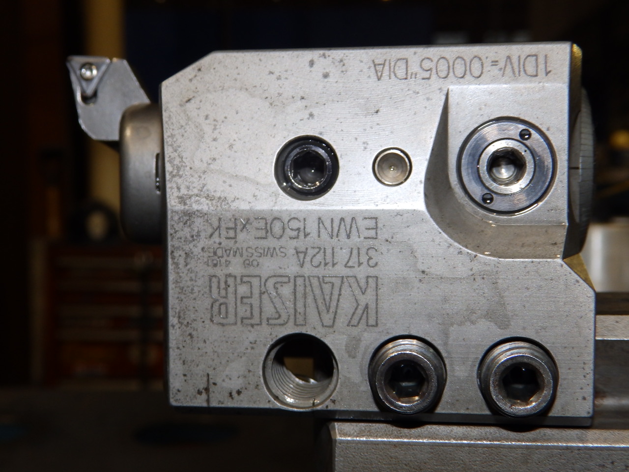
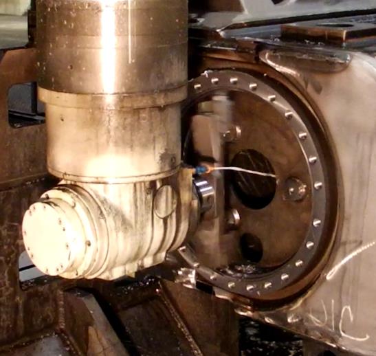
Large machining suppliers will standardize on one or more tools for large boring operations. Big Kaiser is one supplier of large boring tools. These tools are modular and can be setup for a range of bore sizes. Increments of adjustment on the boring heads are typically 0.0005 inches. Fine adjustment of the boring tool is possible even for large bore sizes. Picture # 3 shows the boring tool, picture # 4 is the boring head. Picture # 5 shows the boring operation in process on the large vertical gantry machine.
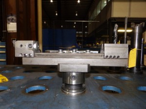
Picture #3 – Boring Tool
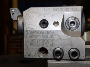
Picture #4 – Boring Head

Picture #5 – Boring Operation on Large Vertical Gantry Machine
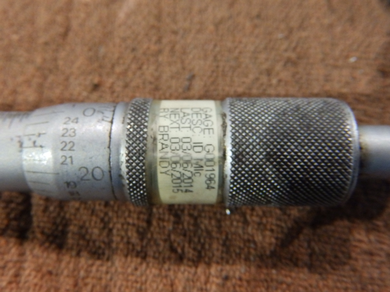
Large bores must be measured accurately to verify the bore diameter meets the customer requirement. Lot sizes are often small (frequently one) in the large machining industry. Gages must be flexible and accurate. ID mics (Internal Diameter Micrometers) are often used to measure bore diameters. These gages are calibrated to a standard in the plant which is traceable to a national or international standard. The ID mic in use to measure the bore is shown in picture # 6. Picture # 7 is a closer shot of the ID mic. The calibration sticker which shows the due date for the next calibration of the ID mic is shown in picture # 8. The calibration due date is 03/06/15; the date of the picture is 02/09/15.
Picture #6 – ID Mic in Use
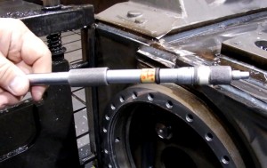
Picture #7 – ID Mic
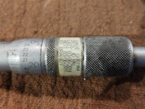
Picture #8 – Calibration Sticker on ID Mic
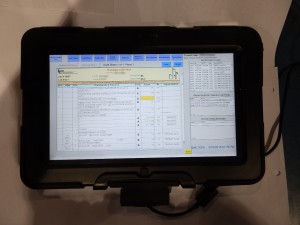
Picture #9 – Tablet Computer for Shop Floor Data Collection
The traceability of the measurement of each large bore diameter to a specific part is desirable and may be required by the customer. The data collection of the bore diameter by the machinist using a gage traceable to a national or international standard, and retention of that data traceable to a specific part serial number by the large machining supplier is a valuable service. Electronic data collection on the shop floor is a cost effective method to capture gage readings and link the data to the specific part. Picture # 9 shows a table computer used on the shop floor by the machinist to record bore diameters and other measurements. This data becomes part of the supplier’s quality information that is tied to the ERP (Enterprise Resource Planning) system. This data can be retrieved in the future based on the serial number of the part that was machined. There may be a need for this information after the part has been in the field for years. A good measurement, data collection, and storage system at the large machining supplier is valuable to the supplier, the customer, and the end user of the product. A video of this boring operation is available below.
February 11, 2017
Continue reading → - Process Controls for Contract Manufacturers of Large Machining and Large Fabrications – Part One – Customer Supplier Interface
This is the first in a series of articles that will explore the process controls that are used by contract manufacturers that specialize in large machining and large fabrications. The focus is on the process controls that may be different for a contract manufacturer of large machining and large fabrications. The intended audience includes buyers, product engineers, manufacturing engineers, quality engineers, and auditors that are dealing with contract manufacturers. The areas where process controls are needed apply to any contract manufacturer of large machining and large fabrications. The process controls that are used as examples are only one possible control method. Process controls are subject to continuous improvement activities and to corrective and preventative action and are constantly evolving.
Part one of this series of articles looks at the interface between the customer and the contract manufacturer of large machining and large fabrications and the control of customer supplied documents. Future articles will explore the process controls for, operator instructions, welding and machining, material traceability, material release to suppliers and scheduling, among other topics.
The company that provides contract manufacturing services for large machining and large fabrications has the following conditions that impact the process controls:
- Low volume – Order quantity can be as low as one piece, production orders for ongoing jobs are typically one to five pieces per week. A high volume production job may be up to five pieces per day.
- Infrequent repeat orders – A repeat order for a part that has been manufactured in the past may be placed several years after the last time a part was produced.
- One time orders – An order may be placed for a part that will never be required in the future.
- High customer mix – Parts for several different customers are in the manufacturing system at the same time.
- High part mix – Many different part numbers are in the manufacturing system at the same time.
- High cost of raw materials – Large parts require large raw materials. Large steel castings can cost $50,000 each. A standard size steel plate one inch thick can cost $3,300.
- Make to firm order – Contract manufacturers of large machining and large fabrications typically build to firm customer order and order materials only for firm customer orders. In some cases a customer will give material authorization for the contract manufacturer to purchase material when the customer has not yet placed a firm order.
- Market volatility – The contract manufacturer is subject to the market volatility that their customers face. When market conditions are bad for the customer, work will be brought into the customer facility or delivery dates for firm orders will be pushed out. When market conditions are good, customers will outsource more work to the contract manufacturer.
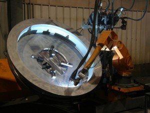
Pictures 1 through 4 are examples of products that are subcontracted to a large machining and large fabrication manufacturer. Picture # 1 is a large fabricated, machined, painted and assembled base for a large CNC router. Each machine is made to order to a specific set of drawings. Other similar machines have been made in the past and may be made in the future, but each is unique, built to the customer’s end-customer requirements. Picture # 2 is a large ductile iron casting for a wind turbine. Production volume reached five pieces per week and every piece is machined to the same customer drawing. Volume rises and falls depending on the customer build rate. Picture # 3 is a large high strength steel fabrication for a winch used in an offshore application. This was a onetime build. Picture # 4 is a large steel fabricated engine block being machined. This is a one-time build, which may repeat years in the future at a different design revision level.
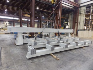
Picture #1 – Large CNC Router
Picture #2 – Large Ductile Iron Casting Machining
Picture #3 – Robotic Welding Large Steel Winch Component
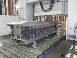
Picture #4 – Machining Large Fabricated Engine Block
The customer interface areas that require process controls and that are important for this type of business are:
Customer quote request – The contract manufacturer deals with many customers. Every customer has different specifications and expectations. It is important that all customer specifications, drawings, and requirements are considered in the quote to the customer. All the customer documents that are used to prepare the quote must be controlled. One method to control the documents that are submitted by the customer for quotation is a location on the company server with controlled access specifically for these documents. Documents are stored by customer name, customer part number and date. Management of these documents is controlled by a designated person. The sales function submits all customer documents that are included with the quote request. As the engineering function works with the customer additional customer documents that are received are submitted to the designate control person for filing. All documents are available for review of a future purchase order or for discussions with the customer. Access to all documents is restricted to the people that need the documents to do their work, for example engineers working with the customer on quotations.
Contract manufacturer’s quote to the customer – The quote to the customer includes documentation of what services and materials are included in the offering, FOB point, delivery date, and price. It also includes any exceptions that are taken to the specifications or requirements that the customer included in the quote request. Process control for this document can be handled in a similar manner to the customer quote request. This is an important document for both the customer and the contract manufacturer. It may be subject to review and discussion at a distant time in the future.
Purchase order – This is the point in the process where there is a contractual commitment by the customer to purchase and the contract manufacturer to deliver. Control of this document is critical. It may be received through EDI (Electronic Data Interface), FAX, mail, or email. One method for process control utilizes a designated person to review the purchase orders for completeness and then entry into the order release system. The designated person compares the purchase order to the quotation to make sure that price, delivery, part number, revision level, quantity, and other requirements match. If there are any differences between the quote and the purchase order they are resolved with the customer prior to order entry. If there are no differences the purchase order is entered into the ERP (Enterprise Resource Planning), MRP (Material Resource Planning) or other system.
Customer drawings and specifications – Now that a purchase order is accepted and entered into the manufacturing system the control of customer documents becomes even more important. The part will be manufactured now and any mistakes made by using the incorrect document can result in costly mistakes. The contract manufacturer must use information from many customers. Each customer has their own print and specification naming convention. The contract manufacturer’s systems must incorporate the diverse naming conventions into a standard convention that all employees can use and understand. ERP and MRP systems utilize a database system. Oracle is an example of a database that is used by ERP and MRP systems. The database of the ERP or MRP system is used to store and control customer information. The ERP/MRP system database can be expanded or connected to other databases used to control all customer documents. This link will give more information on using an Oracle database in conjunction with an ERP system. The data entry function is the process control point for entering customer and other documents into the ERP system. This person is identified in the quality system documentation. Each item entered into the database has access privileges defined. For example manufacturing engineers may be given access to look at obsolete revision levels of drawings, but manufacturing operators and supervisors may be only able to read the current revision level of a print. Only the designated document control person and alternate are given access to add and delete documents from the system. Picture # 5 shows an interface for an Oracle database that is integrated into an ERP system. Customer name and part numbers have been covered. The “Customer Drawings” section is highlighted on the left. Customer drawing numbers are listed on the right. The drawing is opened when the drawing number is selected. You can see the selection of documents on the left hand side that are stored and controlled in this database. Every important document for manufacturing is stored, controlled and accessed from this database, which is available to all employees from CEO to machine operator. Each person has access privileges appropriate for their job function.
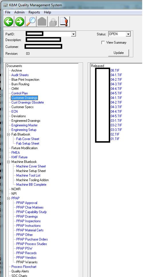
Picture #5 – Interface for Oracle Database
Using this Oracle database integrated with an ERP system, documents are received from the customer and entered by the authorized person and become immediately available by everyone in the contract manufacturing company with authorized access. Only the latest revision level is available for manufacturing on the shop floor. This database can be accessed from desktop computers in the office and tablet computers on the shop floor.
If you are working with a contract manufacturer of large machining and large fabrications you trust the contract manufacturer to provide a quality product, delivered on time, to your requirements. An important part of the job of the contract manufacturer is to control all of the drawings, specifications, and other documents that define your expectations. The process controls that the contract manufacturer has in place are critical to the fulfillment of your expectations.
January 29, 2015
Continue reading → - Large CNC Machining Of Steel Casting – Custom Head for Tight Clearance Milling
Large CNC machining of large steel casting and large steel fabrications frequently requires milling operations in tight spaces where a standard right angle head attachment will not fit. In these cases it is necessary for the machining supplier to purchase a custom right angle head small enough to fit into the available space. Right angle head attachments are available that have a core standardized design that is customized to fit the specific application. This article is a look at an application of a customized right angle head.
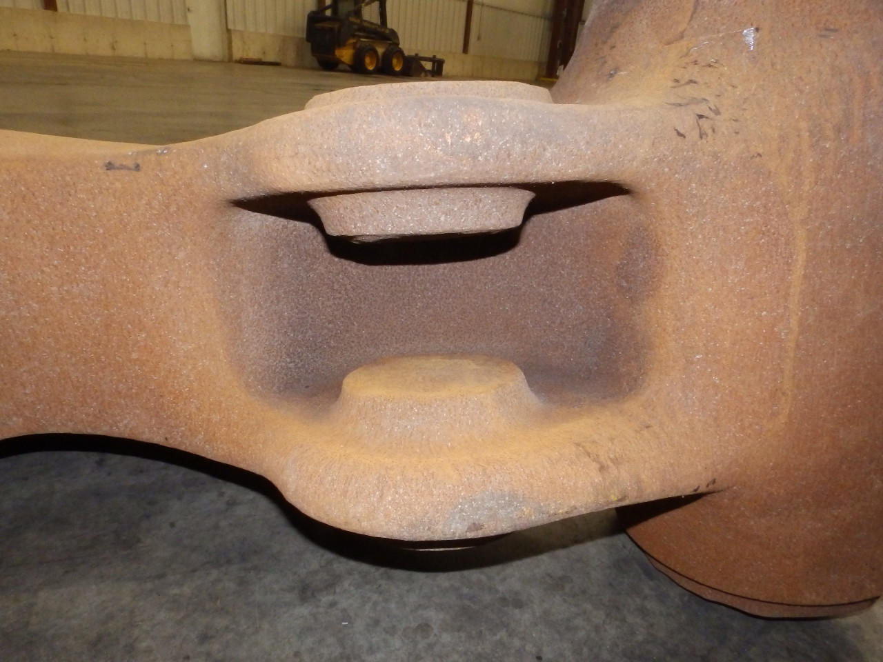
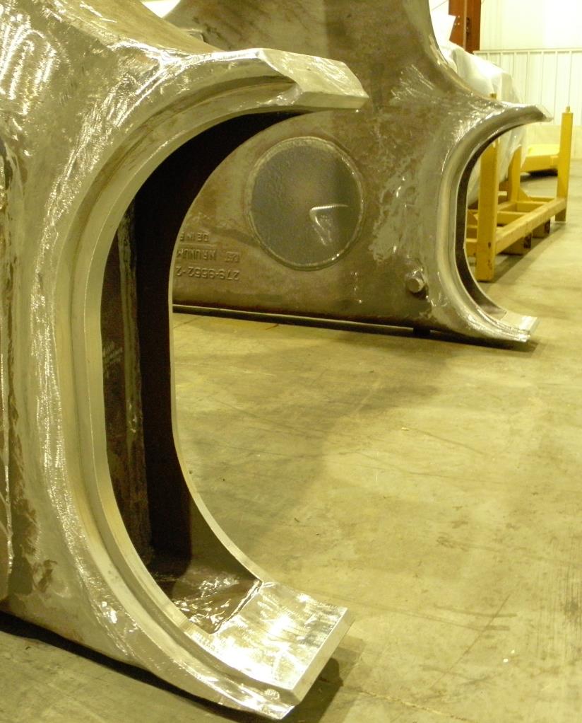
The large steel casting has two faces inside the casting that must be machined. Picture #1 shows the casting and the two faces. There is 399 mm (15.7 inches) of clearance from the finished surface of face two to the top inside diameter of the casting. Picture #2 shows the casting prior to machining. You can see that there is a lot of stock removed from face two. There are also casting ribs inside the casting. Both of these features further restrict the space available for the right angle head and the milling cutter.
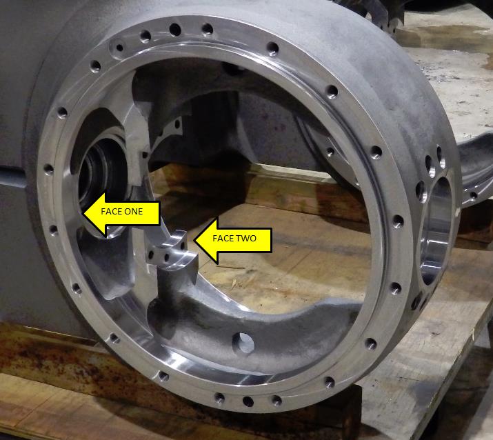
Picture #1 – Two Faces After Milling
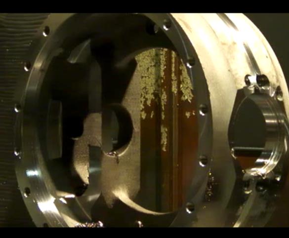
Picture #2 – Faces Before Machining
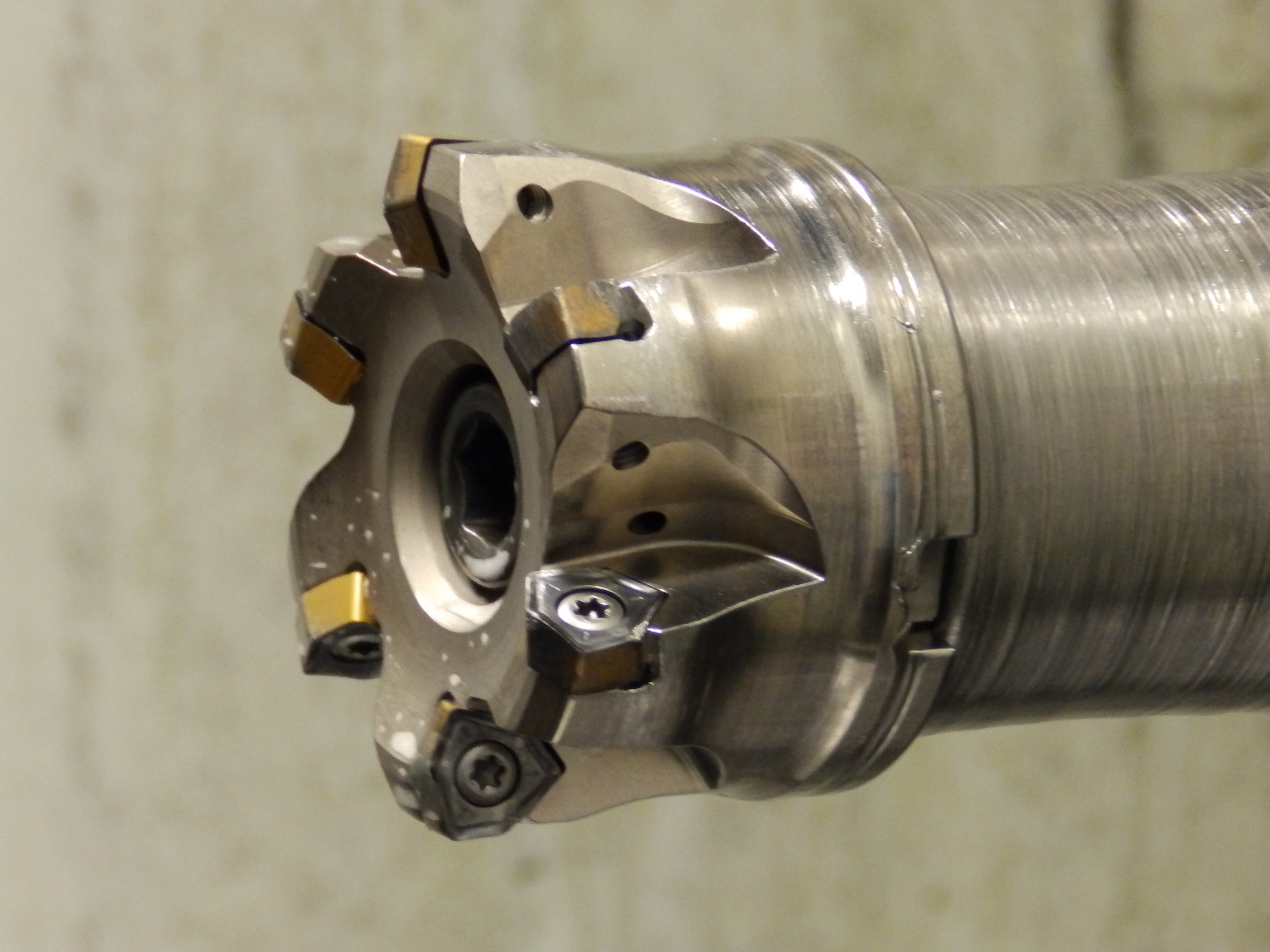
The engineer at the machining supplier uses the casting drawing, machining drawing and the expected variation in casting material to calculate the clearance that is available for the machining operation. He then uses the tool size and machining motion to calculate the maximum size of the right angle head. The supplier of the right angle head is consulted to determine which of their heads can be customized to fit into the space. An adapter will be needed to adapt the right angle head onto the spindle of the large CNC horizontal boring machine. Picture #3 shows the right angle head with tool mounted that was customized for this job.
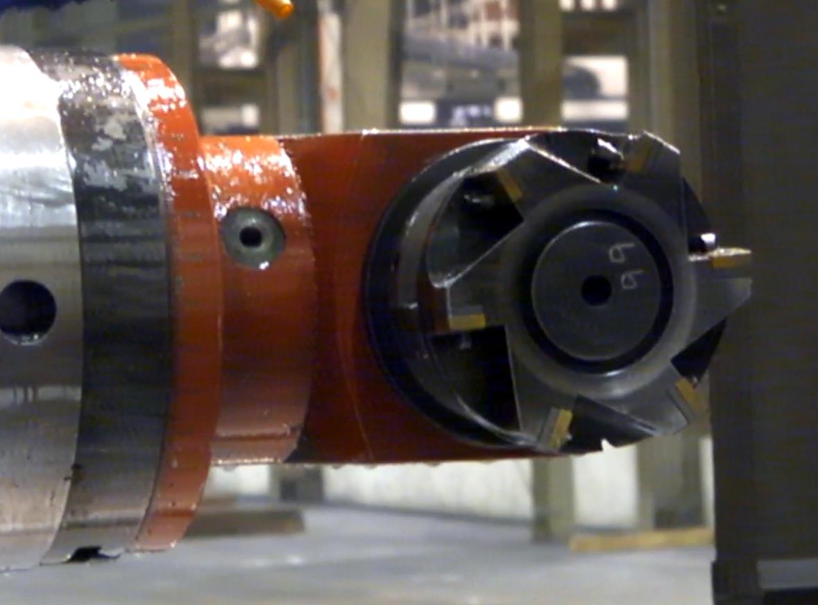
Picture #3 – Custom Right Angle Head with Milling Cutter
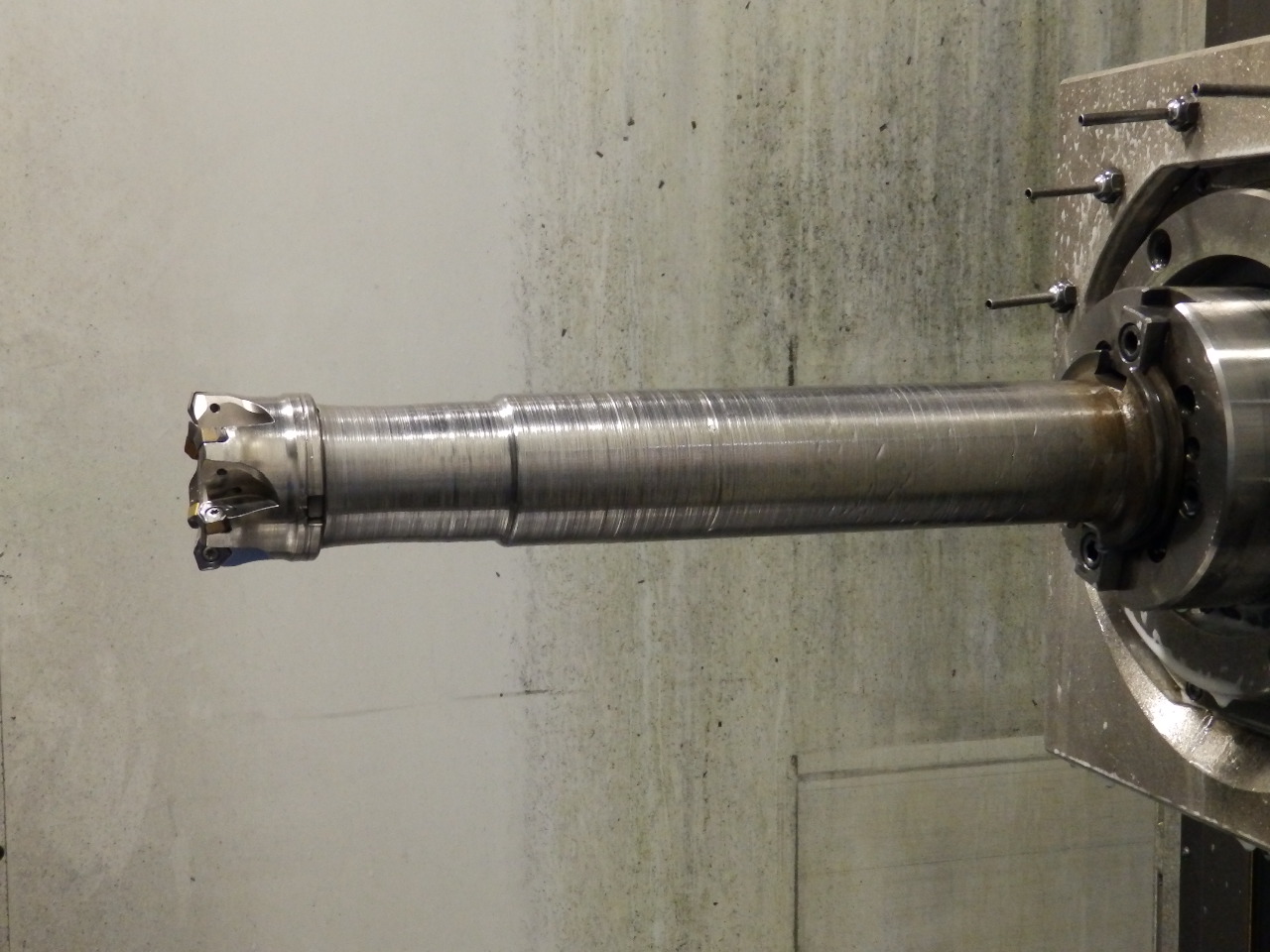
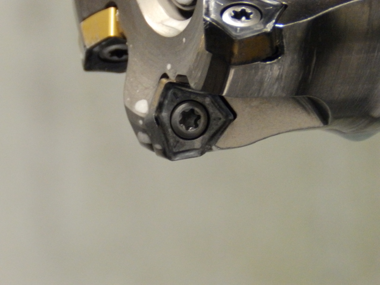
You can see that the width of the head is close to the diameter of the milling cutter. There is a trade off between the diameter of the milling cutter and the envelope that the head will need for travel. The larger the milling cutter the smaller the envelope will be. There is a maximum diameter for the milling cutter to machine the diameter of surfaces to be milled. The custom right angle head is a significant investment. It is important to consider the family of parts that can benefit from the right angle head. The engineer also has to consider potential future applications. The machining engineer works with the engineer at the right angle head supplier to specify the dimensions and other characteristics of the right angle head. Picture #4 shows the right angle head in action.
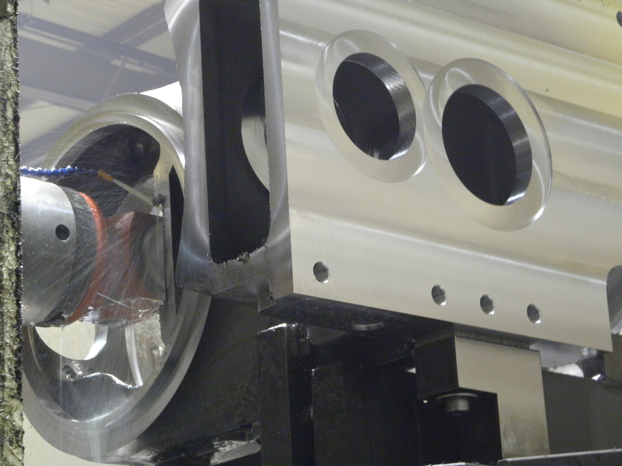
Picture #4 – Right Angle Head in Action
It is difficult to appreciate the tight space that this milling operation works in without seeing it in action. The video below will give you a better idea.
The surfaces milled into this large steel casting are important for the functioning of the final assembled part. The large steel casting design engineer, the machining engineer, and the right angle head engineer all have a role to play to find an economical solution to meet the design requirements of the final part. This is an example of successful collaboration across the supply chain. The contract large machining supplier is at the center of this collaboration.
January 16, 2015
Continue reading → - High Feed Milling Large Steel Castings – Don’t Let Casting Inclusions Disrupt Your Supply Chain
Large steel castings can be subject to inclusions or structural anomalies. These inclusions can cause high tool wear and even catastrophic tool failure. The need to machine 140 mm diameter holes 175 mm deep into a large steel casting with a high frequency of inclusions provided an opportunity to test various tooling solutions. High feed milling proved to be robust to the presence of inclusions in the castings.
According to Key to Metals AG inclusions in steel castings are different in structure from the base metal. The American Foundrymen’s Society Inc. states that inclusions may be caused by de-oxidation or re-oxidation events, presence of refractories or sands used in the casting process, or the emulsification of slag. The root cause of the casting inclusions is the foundry. The foundry is often remote from the machining operation, potentially on a different continent. This distance and inventory makes collaboration between the machining source and the foundry difficult. The correction of the root cause of the casting inclusions will take time and concentrated cooperative effort on the part of the machining source and the foundry. Time waits for no man. Neither does a customer that needs finish machined castings to maintain her production schedule. There is no time to wait for a foundry correction. The machining source must find the best tooling solution to deal with inclusions, meet production schedules, and control costs.
Picture #1 shows a large steel casting that is subject to the presence of inclusions in the locations where 140 mm diameter bores, 174 mm deep must be machined. Picture #2 shows the casting after the machining operation. This operation is one of many welding and machining operations required on a large component. Cutting tool failure due to the presence of inclusions in the casting was causing disruptions to the supply chain and excess machining and tooling costs.
Picture #1 – Raw Casting

Picture #2 – Bores after Machining
Two additional obstacles were present with this operation. It is necessary to reach through one bore to machine the second bore which requires a long extension on the tool. The surfaces perpendicular to the bores that must be machined are not flat.
Drilling is an obvious machining method to machine the bores. Many tool manufacturers offer center cutting drills and inserted drills that can machine these bores. Several different drill designs were tested on this operation. None of the drills tested could stand up to the inclusions. Failure started with high insert wear, then damage to the cartridges that hold the inserts, and finally damage to the drill body itself. Although all of these drills are used successfully in other applications the high frequency of inclusions, long reach and non-flat surface made the drills fail. High feed milling replaced drilling on this operation. Picture #3 shows the Seco 3 inch diameter high feed milling cutter used on this operation. Picture #4 shows the milling cutter mounted on a 16 inch long extension needed to reach the inside bore.
Picture #3 – Seco 3 Inch Diameter High Feed Milling Cutter
Picture #4 – Seco High Feed Milling Cutter on 16 Inch Long Extension
Todd Miller in his article in MoldMaking Technology explains that rigidity of the machine is a key to successful high feed milling. This operation is performed on a Pama Speedmat 4/160 machining center which is equipped with a 160 mm diameter spindle. The 16 inch long extension on the tool is one piece. It was not necessary in this case to use an anti-vibration bar for the extension. A multi-piece extension was tested but was not rigid enough. Picture #5 shows the trigon style insert used in the high feed milling cutter.
Picture #5 – Trigon Style Insert
The geometry of the trigon insert distributes the cutting force along the edge of the feed mill insert. The result is a relatively high chip load per tooth with a relatively thin chip. In steel applications most of the heat generated is taken away with the chip. The typical negative rake geometry used on a high feed milling cutter causes the chip to be pushed away from the cutter body. This geometry also directs cutting forces along the spindle axis and reduces vibration. The video below shows the high feed milling operation.
The cutting parameters are 360 RPM, 2,650 mm/min feed rate around the 140 mm diameter bore. The Z axis feeds at 1 mm per revolution of the cutter around the 140 mm bore. The cycle time to machine the 175 mm deep bore is 7.7 minutes. This setup has proven to be very robust to the presence of inclusions in the casting. Insert wear is predictable and there are no catastrophic tool failures. The result is a stable, in control operation which is critical to a smoothly flowing supply chain.
It is always better to attack a problem at the root cause. In some situations you may not have any control over the root cause. In the case of a machining source with no control over the casting process, expertise in alternative machining methods is critical. The root cause may not be corrected, but an in-control process can be put in place which eliminates a disruption to your supply chain.
January 9, 2015
Continue reading → - Large CNC 3+2 Machining, Lean Manufacturing and the Seven Forms of Waste
Economical and accurate machining of large components can be achieved using large CNC machines and the 3+2 machining technique. This article will examine 3+2 machining and relate the economical and quality benefits in terms of lean manufacturing’s seven forms of wastes.
3+2 machining refers to the use of a 5 axis CNC machine in a specific manner. In 3+2 machining two of the axes are locked into a fixed position and the remaining three axes are moved under program control. For example the spindle centerline on a universal head on a vertical gantry mill may be positioned and locked relative to the X, Y, and Z coordinate system of the machine. From this position the universal head spindle axis becomes the Z1 axis with the X1 and Y1 axes perpendicular to this Z1 axis. The machine is then programmed and moved relative to this new coordinate system. The CNC program moves the machine X, Y and Z axes simultaneously to produce motion in the X1, Y1 and Z1 axes created relative to the universal head spindle centerline. CNC controls on machines designed for 3+2 programs are equipped with subprograms that allow the CNC programmer to write 3 axis code relative to the new coordinate system (X1, Y1, Z1). The control subprograms translate the 3 axis X1, Y1, and Z1 program code into the machine movement commands for the machine X, Y, and Z axes.
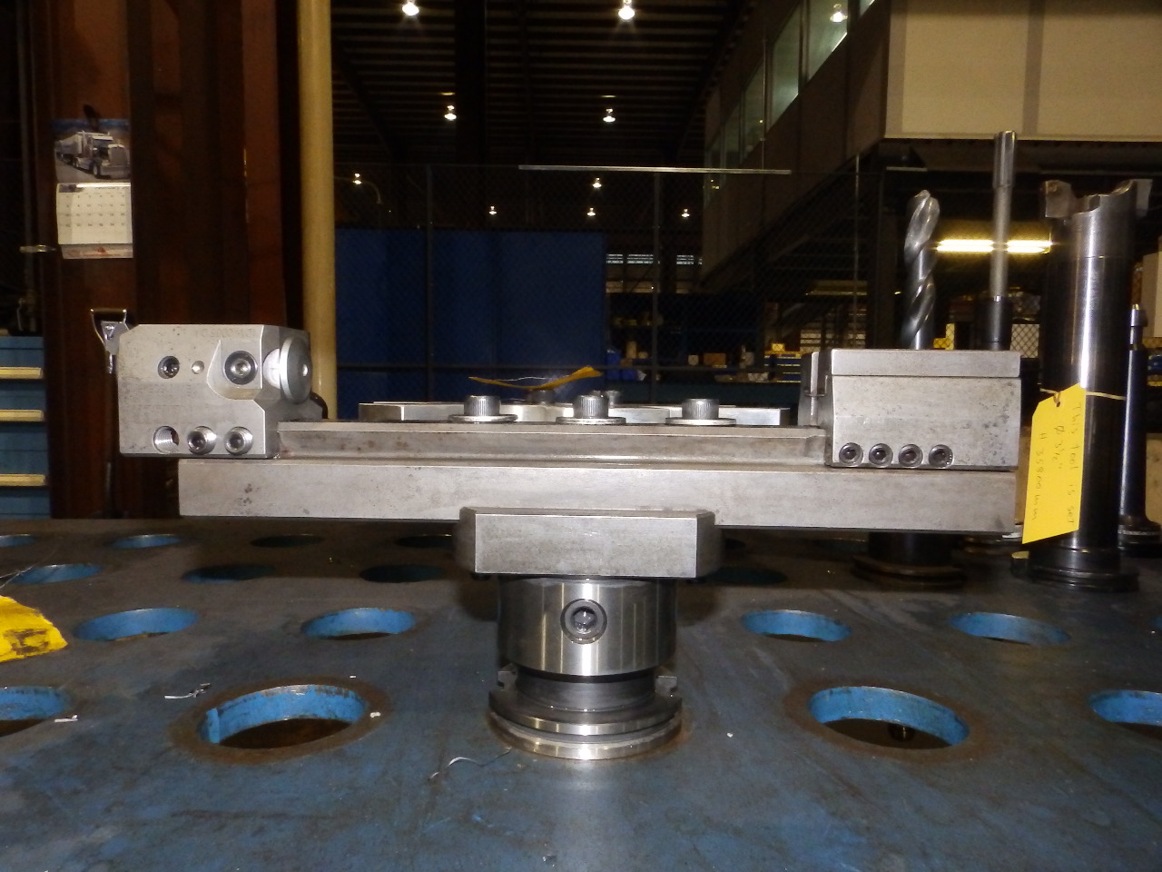
3+2 machining differs from 5 axis machining. 5 axis machining involves the simultaneous motion of 5 axes during the cutting process. In 3+2 machining two axes are fixed and there is simultaneous motion of only three axes. An example of an ideal part for 3+2 machining is shown in Picture #1. This picture shows two of the four sets of two bores each. Each set of bores has machined inside and outside faces. The bores and the faces of each set of bores are offset at a different angle to each of the X, Y and Z axis of the locators and the gantry machine. Without 3+2 machining at least four setups would be required instead of the one setup possible with 3+2 machining.
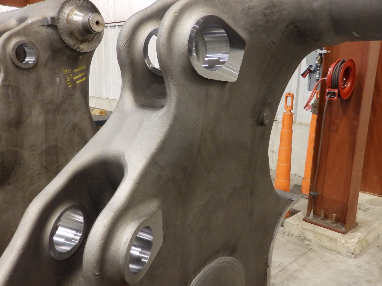
Picture #1 – Large Component with Bores and Faces Offset at Angles to X, Y, Z Axes
Machines used for 3+2 machining have 5 axes. Why is 3+2 machining used when 5 axis machining could be used? There are several reasons. For large CNC machines used to machine large components the guide ways for the X, Y and Z axis are designed and built for heavy stock removal and speed. Hydrostatic guide ways are commonly used. The universal head on a large CNC vertical gantry mill or large CNC boring mill is designed and built for flexibility and to fit into relatively tight spaces. It is not designed for heavy cutting loads during movement of its two axes of motion. By locking the two axes of motion on the universal head it becomes more rigid and capable of handling higher cutting forces. It can still not handle the maximum cutting forces that can be generated by the X, Y and Z axis, but it can handle more than if it was not locked. 3+2 machining, where it can be used, allows higher cutting forces and higher cutting speed than 5 axis machining. Programming for 3+2 machining is simpler than 5 axis machining programming. The CNC programmer can program in three axes using the machine control subprogram. To the programmer 3+2 machining programming is like 3 axis programming. There are CAM software packages that automate the 3+2 programming, but manual G code programming is possible. 5 axis machining requires the use of a CAM software package for programming.
Picture #2 shows a large vertical gantry mill using 3+2 machining with a universal head. Picture #3 is a picture of the same machine, an SNK RB-7VM Vertical Gantry Machine.
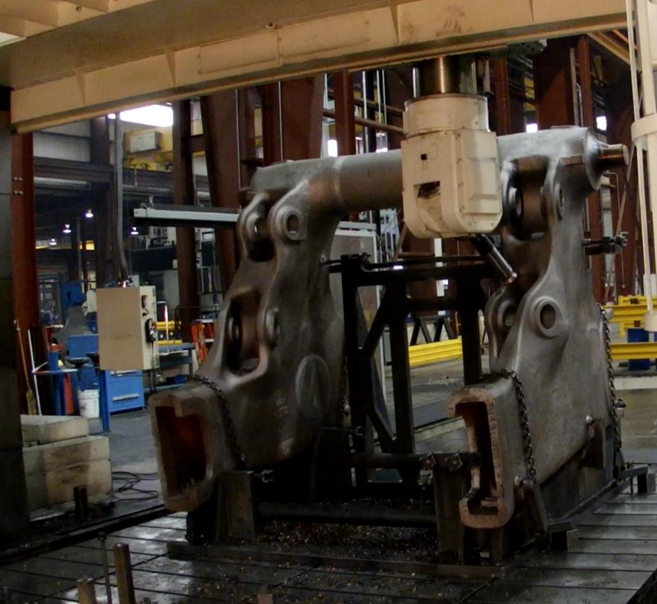
Picture #2 Large Vertical Gantry Machine – 3+2 Machining
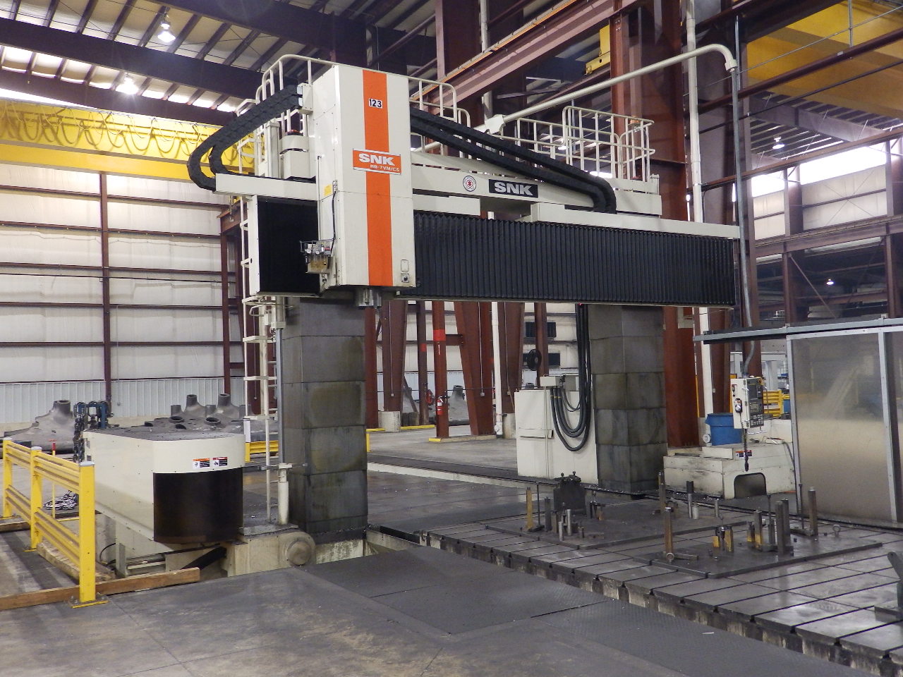
Picture #3 – Large Vertical Gantry Machine – SNK RB7-VM
A video of 3+2 machining of the part shown in Picture #2 may be viewed below.
You can machine five sides of a large component in one setup when you use 3+2 machining. You can machine along axes that are not perpendicular to the X, Y and Z axes of the large CNC machine. There are advantages to 3+2 machining on any size component, but for large components the advantages are greatly multiplied. Consider the seven forms of waste that are a cornerstone of lean manufacturing
Waste of defects – Variation in dimensional results in machining are a form of the waste of defects. If the variation causes an out of print condition the work piece must be repaired, scrapped or deviated by the customer. Even if the out of print condition is accepted by the customer there is the potential cost of less than ideal performance of the part in the field or the real cost of time spent considering the deviation request and the loss of credibility and trust on the part of the supplier. 3+2 machining reduces the number of setups required to finish machine a component. Setups add to variation. Elimination of setups reduces variation and defects. Large components are more costly than small components. The repair costs or cost to scrap are much greater on large components.
Waste of transportation – The reduction of setups that is possible with 3+2 machining reduces the number of times a part must be moved between machines for different operations. Large components are more costly to move than small components.
Waste of inventory – When multiple setups on the same or multiple machines are required there must be in-process inventory present to maintain the flow of parts. When setups are eliminated the in-process inventory between setups is eliminated. Large components are expensive. The waste of inventory is expensive.
Waste of motion – Motion can be consider the motion of the machine operator. Setups, especially for large components, require work, and motion on the part of the machine operator. Eliminating setups eliminates operator motion.
Waste of waiting – Parts wait between machines and on the machine during setup. The machine waits during setup. No cutting action or value added work is being performed while a setup is in process. Large CNC machines required for large components are expensive. The operators for these machines are skilled. Elimination of setups reduces the high cost of waiting.
Waste of over processing – When multiple setups are required to complete machining there are tolerance stack ups in the relationship of the features in one setup to the features in a different setup. In order to maintain the desired tolerance between features machined in different setups it may be necessary to hold a tighter tolerance in each individual setup. This tighter tolerance in each setup is over processing that is not required in the single setup of 3+2 machining.
Waste of over production – When machining in multiple setups there may be multiple machines involved and inventory between operations. Each machine in the process has the potential to over produce in order to keep the machine running. With a single setup in 3+2 machining there is only one setup and no opportunity to overproduce in any operation other than the final operation.
You can see that 3+2 machining fits into the lean manufacturing philosophy. It is a very flexible and lean process, especially when machining large components. The larger the component, the greater the potential reduction in waste. Large CNC machines capable of 3+2 machining are expensive and have a long lead time to purchase and install. If your product requires large components that can benefit from 3+2 machining but you do not have the volume to justify a machine or you do not have the lead time to wait for a machine, consider using a contract machining source that specializes in 3+2 machining of large components. These companies are in the business of having capacity available on short notice. They combine work from several customers to load work onto the machines. You can take advantage of the benefits of 3+2 machining on large components without the capital investment, learning curve or lead time.
January 5, 2015
Continue reading → - Large Fabrication Submerged Arc Welding (SAW)
Submerged arc welding is a proven processes with many benefits, including high productivity and high quality. It is particularly suited to welding on large fabrications in series production. There are a number of process steps that are important during the SAW welding process to insure that high quality welds are produced. K&M Machine-Fabricating, Inc. uses the SAW process to weld large fabrications for series production.
Submerged arc welding was first used in the 1930’s. Today’s SAW equipment and processes are the result of many years of production use and improvements. Advantages of the SAW process are high deposition rates, deep weld penetration, and high productivity.
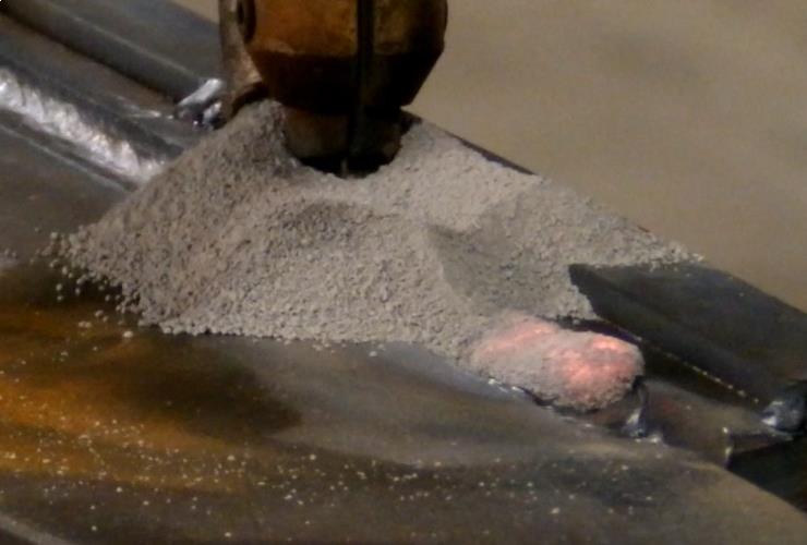
The SAW process is similar to the MIG (Metal Inert Gas welding). The SAW process uses a flux that is granular. The flux is used to generate shielding gases and slag and to add alloying elements to the weld pool. Picture # 1 shows the flux around the welding electrode.
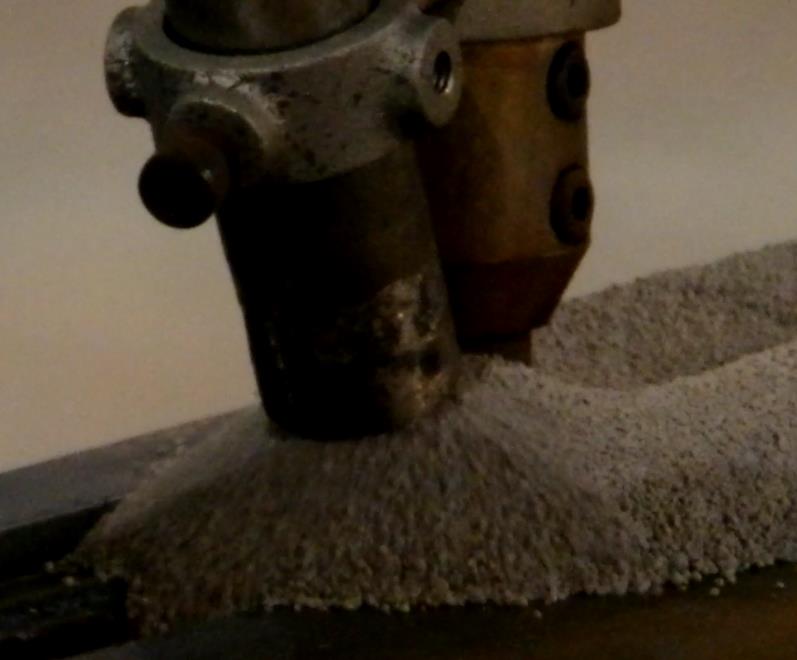
Picture # 1 – Flux Deposited in Front of Welding ElectrodeK&M Machine-Fabricating, Inc. has two ESAB CaB300 Sub Arc machines. Each of these machines features a 3 meter column travel, 3 meter boom travel and they are mounted on a 50 foot long rail carriage. The size and travel of these machines are well suited for welding large fabrications. The machines are equipped with joint tracking and positioning capability. The welding heads are 1250 Amps. The Plasma gouging heads are 150 amp. The K&M Youtube channel features a video of the Subarc machine in action (link). This article will describe the Subarc process that is featured in the video. Picture # 2 below shows one of the subarc machines at K&M. The large fabrication that is in process is shown located to the right of the subarc machine.
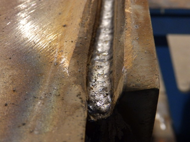
Picture # 2 – Subarc Machine at K&M with Large Fabrication in LocationThe weld demonstrated in the K&M video is typical of the welds produced using the subarc process at K&M. This joint is a 60 degree bevel. This weld joint requires 100% penetration and 100% UT inspection. Prior to positioning in the subarc machine a backing weld is applied to the weld joint on the large fabrication. Picture # 3 shows the weld joint prior to the plasma gouging and subarc welding that takes place on the subarc machine.
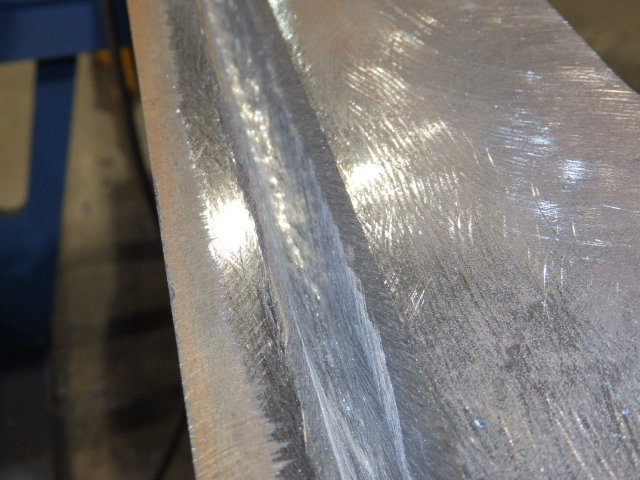
Picture #3 – Weld Joint Prior to Plasma GougingThe first step in the welding process for the large fabrication on the sub arc machine is to plasma gouge the joint. This process is required to insure that 100% penetration is achieved in the welding process. Picture # 4 shows the weld joint after plasma gouging.
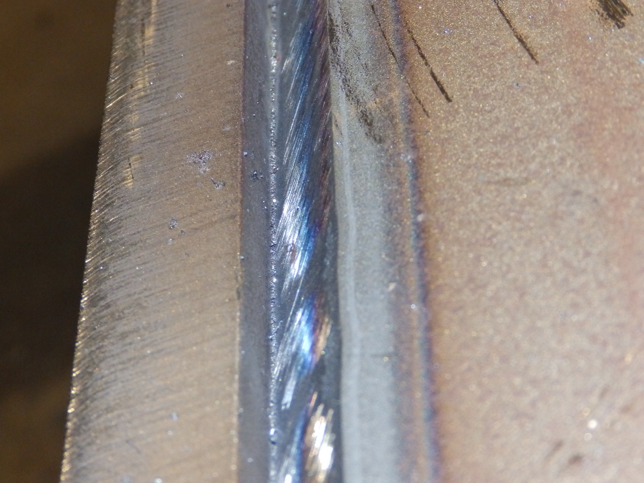
Picture # 4 – Weld Joint After Plasma GougingAfter the plasma gouging operation the weld joint is ground with a grinding wheel to clean the joint and to achieve the proper weld joint geometry. The weld joint geometry is checked with a template gage. Picture # 5 shows the weld joint after grinding. The weld joint is also cleaned with a wire wheel.
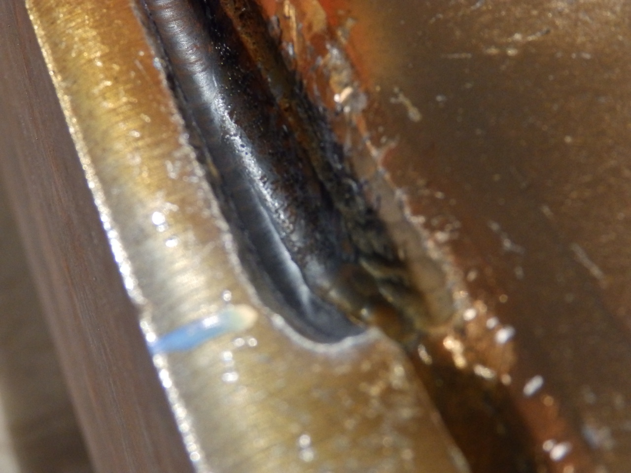
Picture # 5 – Weld Joint After GrindingA root pass is applied to the weld joint with the Flux Core (FCAW) welding process prior to welding with the sub arc machine and sub arc process. Picture # 6 shows the root pass in place in the weld joint.
Picture # 6 – Root PassThe weld is cleaned with a chipping hammer and wire wheel after the root pass and between all SAW weld passes. After cleaning the first SAW pass is welded. Picture #7 shows the SAW welding in-process. The cooling molten slag can be seen to the right of the picture.
Picture # 7 – SAW Welding in ProcessOn a large fabrication the size of the weld joint will often require multiple SAW passes. Interpass cleaning and inspection is a critical part of the welding process. Any irregularities must be found between passes. Finding indications after all passes are complete will require repair of the weld joint. Repair costs will detract from the cost savings that were achieved by using the SAW process. Picture # 8 shows multiple passes and cap passes.
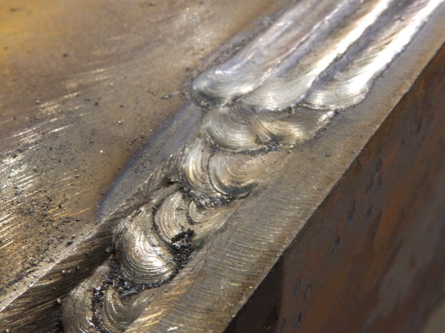
Picture # 8 – Multiple SAW PassesThe SAW process produces a weld that is visually appealing. Not only is it a high quality weld (these welds are 100% UT inspected), it looks like a high quality weld. Picture #9 shows the finished weld after the cap passes are complete. K&M’s customers, their customers, and the user in the field appreciate the high quality and good visual appearance of the SAW welds.
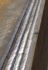
Picture #9 – Cap PassesThe SAW process is one of the many welding processes that K&M uses to manufacture large fabrications. The same focus on welding processes and quality that is used in the SAW process is used in all of K&M welding processes.
K&M’s video showing Large Fabrication Submerged Arc Welding (SAW)
November 24, 2014
Continue reading → - Large Machining of Weld Joint Surfaces for Large Fabrications
Many of the criteria for designing the weld joints for robotic welding apply to designing weld joints for manual welding in large fabrications. According to the American Welding Society weld joints must be repeatable for robotic welding to be successful. The same is true for welding large fabrications. The designer of large fabrications can chose to specify a machined weld joint or the designer can chose a cast weld joint surface on a casting or a plasma, oxyfuel, or laser cut weld joint surface on a plate burnout. Although a machined joint surface will increase the cost of a component, the savings in weld rework, rejection, and potential weld failure more than pays for the added cost. For large fabrications, large machining is required to produce the machined weld joint surfaces.
A large top level fabrication is typically made up of several smaller fabrications. These smaller fabrications can be 20 feet long with a fabrication tolerance of plus or minus 1/8 inch. When a fixture is used to locate these fabrications to each other the variation between the weld joint faces can vary plus or minus ¼ inch, or a range of ½ inch. A gap of less than zero is not allowed, so the gap can be as large as ½ inch. This is not a feasible condition for welding.
Robotic welding technology exists to overcome variation in the location of the welding joint. These technologies include touch sensing, through-the-arc tracking and vision systems. All of these systems are available proven technologies that are available for a cost. The one aspect of weld joint variation these systems do not overcome is the case of a large weld gap. The consequences of a large gap can be undersize welds, poor fusion, or inability to complete the weld. This translates into increased welding time, weld repair time, or poor quality welds. All of these consequences are costly. There is an alternative that greatly reduces the weld joint surface variation and eliminates the large weld gap. That alternative is to machine the weld joints on the large fabrication. Picture 1 shows a machined weld joint on a fabrication composed of two castings. Picture 2 shows a 20 foot long fabrication fixtured in a Large Vertical Gantry Mill for machining of all weld joint surfaces in a single setup.
Picture # 1 – Machined Weld Joint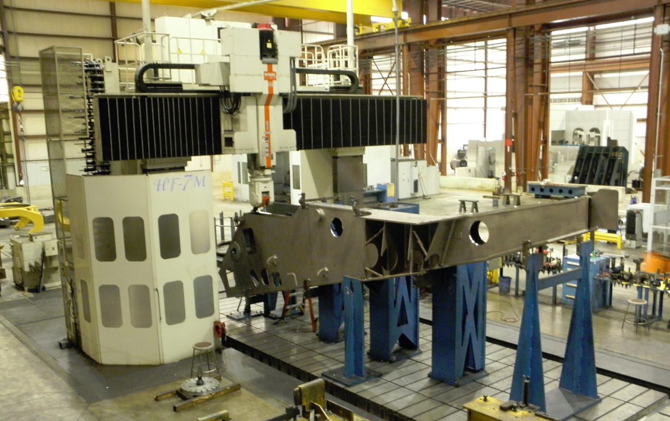
Picture # 2 – Machine All Weld Joint Surfaces on 20 Foot FabricationThe concept of using machined weld joints on large fabrications involves the specification of location and profile of the weld joint surfaces in relation to datums that are identified on the fabrication. These datums are used to locate the fabrication or casting for machining and the same datums are used to locate the fabrication or casting for final fit up and welding at the top level of the fabrication. Profile tolerances of plus or minus 0.002 inch are achievable with modern machining equipment. This will yield a variation of plus or minus 0.004 inches in the fit up of two weld joint surfaces. The potential gap is 0.008 inches. Compare this to the potential 0.5 inch gap on a joint that is not machined.
Weld joint surface designs may be at compound angles to the datums on the fabrication or casting. Machining equipment with right angle and/or universal heads will be required to produce the required weld joint geometry economically. This is done by machining all weld joints on a fabrication or casting in a single setup. The single setup also reduces the variation between weld joints on the same fabrication or casting.
K&M Machine-Fabricating Inc. has several large horizontal boring mills and large vertical gantry mills that are used to machine weld joint surfaces on large fabrications and large castings. View a video of large machining of weld joint surfaces on K&M Youtube channel.
K&M’s video showing Large Fabrication Submerged Arc Welding (SAW)
November 19, 2014
Continue reading →