Large Machining Articles
Contact Information
Sales Engineer
(269) 445-2495
Large Machining Article Index
- Large Machining Simulation
- Large Machining Capacity Strategy to Meet Changes in Demand
- Large Machining of Base Fabrication for Machine Tools
- Large Machining of Weld Joint Surfaces for Large Fabrications
Large Machining Simulation
The use of simulation software to verify CNC machining programs is a cost effective method to reduce costs and improve quality. This is especially true when machining large fabrications or machining large castings. In many cases weld repair is not allowed on the work piece and any mistake in machining will result in a high cost of quality and delivery delays.
There are several CNC machining simulation packages available. This is a proven technology. There are steps the user of a CNC machining simulation package must take to tailor the software package to the specific machines, programming practices and tooling of the user.
Large CNC machines frequently have multiple axes that operate following specific rules that are specified by the machine builder or the control manufacturer. The CNC programmers also have company standard practices that are used when programming their machines. All of these rules and common practices are incorporated into a post processor that is specific to the machine, control and company that is using the machine. This post processor is used by the simulation software to insure that the simulation results accurately reflect the actual machining operations. The tooling that will be used for the machining operation must be accurately represented in the CNC machining simulation. This is accomplished by importing solid models of the tooling. Many tooling manufacturers have solid models of their tooling that can be downloaded. In other cases the user must create the solid models. Two other aspects of the machining operation can be modeled by the simulation software. These are the fixture and the physical restrictions of the machine itself. Adding solid models of these aspects will enhance the value of the simulation model.
One benefit of the simulation of CNC machining is preventing programming errors from reaching the shop floor. Errors in CNC machining that reach the shop floor can result in crashes between the work piece, tooling, fixture, and/or machine. Errors can also result in excess machining, insufficient machining, wasted machine moves, and downtime to debug programs. All of these errors can be seen and corrected during the CNC machining simulation.
The CNC simulation software begins with two solid models of the work piece. One model represents the work piece prior to machining (raw) and one model represents the desired finished work piece. The simulation drives the cutting tools around the solid model of the raw work piece. The result is a model of the raw work piece after the CNC program has been run. This model is compared to the model of the desired finished work piece. The areas where the machining does not meet the model of the desired finished work piece are visually identified. This includes areas where too much material has been removed and areas where there has not been enough material removed. The CNC programmer then modifies the CNC program and repeats the simulation until the CNC program produces a part that meets the desired finished product in the simulation.
Simulation is beneficial for all sizes of CNC machining but especially for machining large fabrications or machining large castings. In the case of machining large fabrications or castings the cycle time can be measured in hours rather than seconds as is common with small work pieces. Frequently the cycle time to machine one part can take multiple shifts. If the CNC program is proven out during the first piece run without the benefit of simulation the cost to run a first piece will be double or triple what the cost will be for a first piece run that has gone through the simulation process. Machining large work pieces requires large machines. Complex large fabrications and large castings typically require large machines with five axis capability and head changers. These large multi-axis machines have a high cost per hour to operate. The savings achieved by proving out a CNC program with a simulation package versus proving out the program on the machine is substantial. The typical lot size when machining large fabrications and machining large castings is small. Frequently, the lot size is only one or two pieces. The large savings in prove out cost spread over a small lot size results in a significant savings per piece.
The setup time for machining a large fabrication or a large casting is also a substantial part of the time required to machine the part. It is critical that the machining is correct the first time. Any errors must be corrected on the machine. If the error is found in inspection after the work piece has been removed from the machine, then the work piece will have to be set up on the machine a second time for the repair operation. Given the high cost per hour of large machines, this added setup time and repair time are very costly. Simulation of CNC machining operations and comparison of the raw model as machined to the desired finished model greatly reduces the chance of a machining error that will require repairs.
There are cases where any repair operation requires customer approval of a specific repair procedure. In these cases the work piece sits on the machine while the customer is consulted and a repair procedure is approved. The cost for this repair will include the cost to engage the customer as well as the cost to complete the repair operation. The use of the simulation of CNC machining greatly reduces the probability that this type of error will be made.
Companies that machine large fabrications and large castings are judged by their customers on quality, delivery and cost performance. They must use the technology that is available to provide the highest quality, delivery and cost performance. The use of simulation software to verify CNC machining programs is a cost effective way to prevent errors. It is one of the many tools that K&M Machine-Fabricating Inc. uses to meet and exceed customer expectations. See the Large Machining Simulation video below.
Back to the Large Machining Article Index
Large Machining Capacity Strategy to Meet Changes in Demand
Machining of large fabrications and castings is required by many industries. These include the mining, oil and gas, agriculture, construction and machine tool industries. All of these industries are subject to changes in demand. Manufacturing companies that operate in these industries must be able to adjust capacity, up or down, to meet the market demand if they are going to grow when the market is up and if they are going to control costs when the market goes down. The equipment and infrastructure that is required for large machining is expensive and subject to a long lead time to install. This equipment has a long useful life after it is installed. One strategy used by many successful industrial companies is subcontracting of large machining work to meet changes in demand. The current boom in the production of natural gas and oil in the US, the rapid increase in the demand for supporting large machining capacity, and the use of outsourcing by successful companies is a good case study of the application of this strategy.
Horizontal drilling and hydraulic fracturing drilling techniques were developed in Texas after 2000. Since 2004 the production of oil products in the United States has increased 56%. The United States currently produces 12.9 million barrels per day of oil products, leading Saudi Arabia which produces 11.6 million barrels per day. (Source Wall Street Journal 10-15-14). Hydraulic fracturing uses high pressure pumps to force mixtures containing sand into the well. This high pressure and abrasive fluid result in fast wear and short life for the components of the high pressure pump. The high pressure component subject to this short life is the fluid end. The rapidly increasing production of oil and gas in the US and the use of higher pressures and more abrasive fluids have led to rapid growth in the demand for fluid end machining.
Fluid ends are manufactured by many OEMs and supporting companies in the oil and gas industry. The number of companies designing fluid ends and the variety of applications of fluid ends results in many design variations. There are some commonalities in the designs. The majority of fluid ends are made from steel forgings. Fluid ends can require 100 hours of machining time to go from the raw forging state to the finish machined state ready for assembly. The machining operations are divided into stages.
Stage one is the rough machining of the forged blocks. A typical forged block is 270 inches by 25 inches by 20 inches in size and weighing roughly 40,000 pounds. At this stage there is high stock removal and requirements for equal stock removal on each side and a good surface finish. The surface finish is required for subsequent UT (Ultrasonic inspection) of the rough machined block to insure there are no material defects. Figure 1 is an example of a stage one forged block before and after machining. Figure 2 is an example of a large CNC machine during stage one machining.
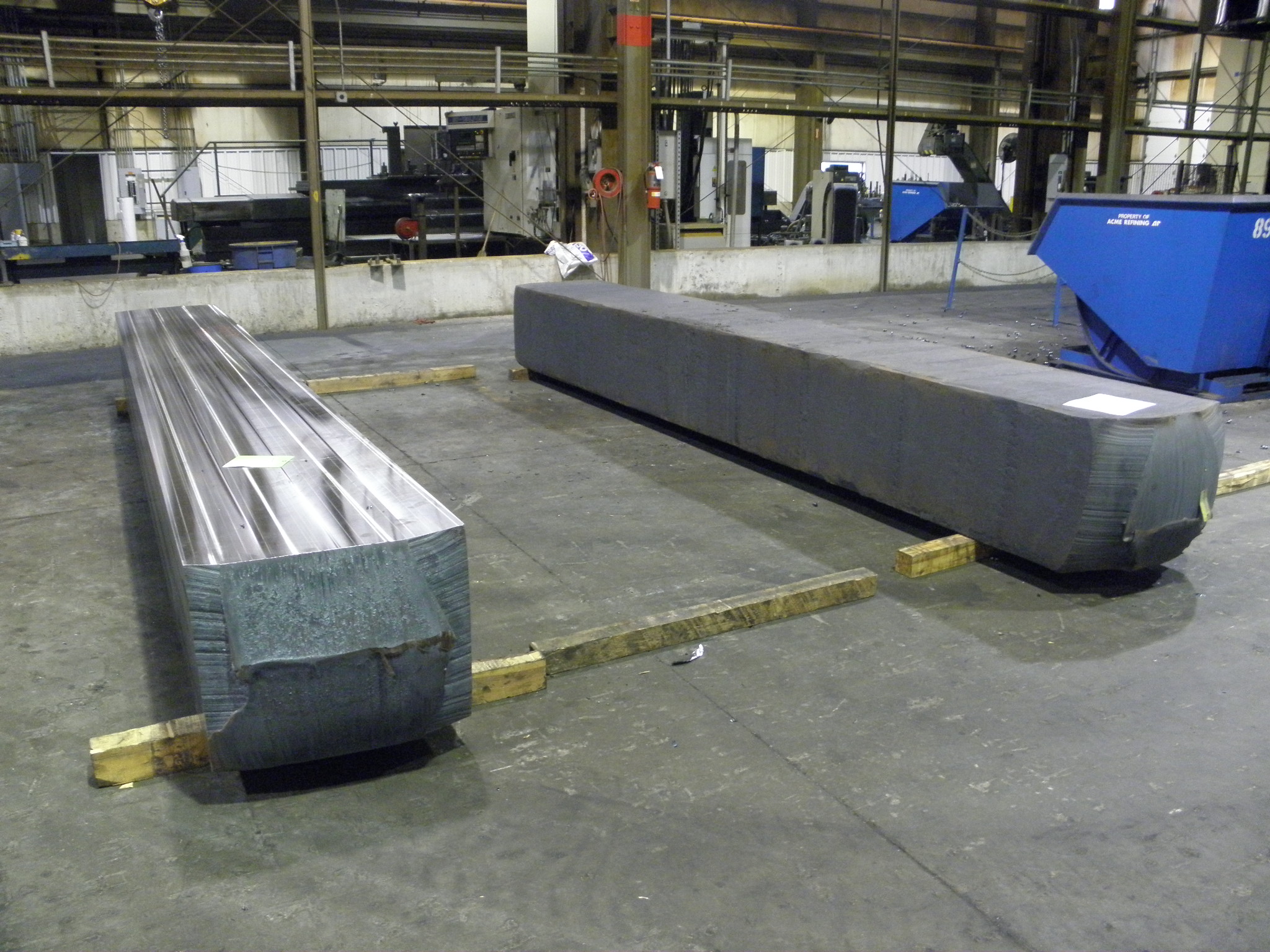
Figure 1 – Forged Block Before and After Machining
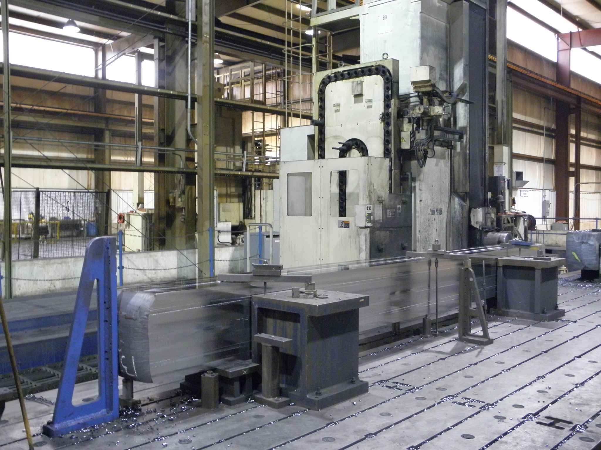
Figure 2 – Stage One Machining In Process
Stage two consists of sawing the rough machined block into sections of the proper length for the particular fluid end design.
Stage three consists of the rough machining of the cube into a shape that is near to the final shape required. Large amounts of material are removed at this stage.
Stage four is the semi-finish operation. All but the final very critical operations are completed at this stage.
Stage five is the final machining operation. Contouring of the bores in the fluid end is completed at this stage. Special equipment on the machine tool is required to complete this operation.
The capacity strategy employed by some successful manufacturers of fluid ends is to install capacity for stage five operations that will meet demand when it is at the expected peak. When demand is high the manufacturing will utilize internal capacity for stage five, final machining operations, only. Stage one, two, three, and four operations are outsourced. When demand decreases the manufacturer will bring stage four operations and potentially stage three operations in house to keep the internal capacity utilized. The fluid end manufacturer maintains a high level of equipment utilization. The fluctuation in large machining capacity utilization is pushed out into the companies that specialize in providing outsourced large machining capacity.
Companies that specialize in providing large machining capacity to the fluid end and other manufacturers have unique characteristics. Their equipment must be flexible in order to serve a wide variety of industries and part types. They must have capacity available. Lead time for machining equipment can be 24 months. When a customer needs capacity, they need it within a short lead time. The contract machining specialist must deliver high quality products with a quick startup time to first piece production and short turnaround time from raw material to shipment of final product.
K&M Machine-Fabricating, Inc. located in Cassopolis Michigan is a company that specializes in subcontract large machining services. They have customers in the oil and gas, mining, machine tool, and other industries. K&M has recently dedicated several machines to the stage one rough machining of forged blocks to support the increased demand from fluid end manufacturers. See the video below of Rough CNC Machining of Forged Blocks for Fluid Ends.
Back to the Large Machining Article Index
Large Machining of Base Fabrication for Machine Tools
The base of a machine tool is critical to the performance of the machine tool. A large surface grinding machine may have a required positional accuracy of 0.005 mm on all axes. This accuracy must be maintained over the life of the grinder and during metal removal operations. Many components of the machine tool contribute to this accuracy. The base of the machine is the foundation upon which rests all other components in the grinding machine. Accuracy of the final machining operation on the machine tool base is required in order for the finished grinding machine to deliver the required 0.005 mm positioning accuracy. Use of a large CNC vertical gantry mill, like the Mitsubishi MVR43/49 Dx at K&M Machine-Fabricating Inc. is an economical and high quality method to achieve the required accuracy.
The purpose of the machine base in a machine tool is to provide a stable foundation for the operations that will be performed. The functions of the structure of the machine tool base are:
- Carry static and dynamic loads without distortion
- Assure that all moving parts are stable and move accurately
- Resist wear caused by moving parts
- Dampen vibration from machine tool operations
- Assure stability of the structure through the elimination of residual stress during construction
These functions of the machine tool structure are defined in Youssef and Hofy 2008 publication Machining Technology Machine Tools and Operations published by CRC Press in 2008 ().
The provider of outsourced machined steel fabrication services for large fabrications used in machine tool structures must take several steps to insure that the characteristics of the fabrication design are realized in the machine tool structure that is delivered to the customer. These steps include:
- Analysis of the customer requirements through review of drawings and specifications.
- Planning the manufacturing process.
- Sourcing of the steel plate and other materials.
- Cutting the steel plates to the design dimensions and tolerances and completing other secondary operations.
- Tack welding the structure to the in-process dimensions leaving material as required for final machining operations.
- Welding the structure to meet dimensional requirements and structural integrity requirements.
- Stress relieving the structure.
- Machining of the structure to meet dimensional requirements.
- Paint to the customer’s specification.
- Perform inspections.
The large vertical gantry mill is an ideal machine tool to perform the large machining that is required on a large grinder base. The Mitsubishi MVR43/49 Dx vertical gantry mill is large enough to handle the base in a single clamping. It is equipped with two right angle heads and a universal head. Using these heads it is possible to machine five sides of the work piece without moving the work piece. No variation in location or parallelism between features and surfaces will be induced by moving the fabrication between machining operations. Figure 1 shows a large grinder base during machining on the Mitsubishi MVR43/49 Dx vertical gantry mill.
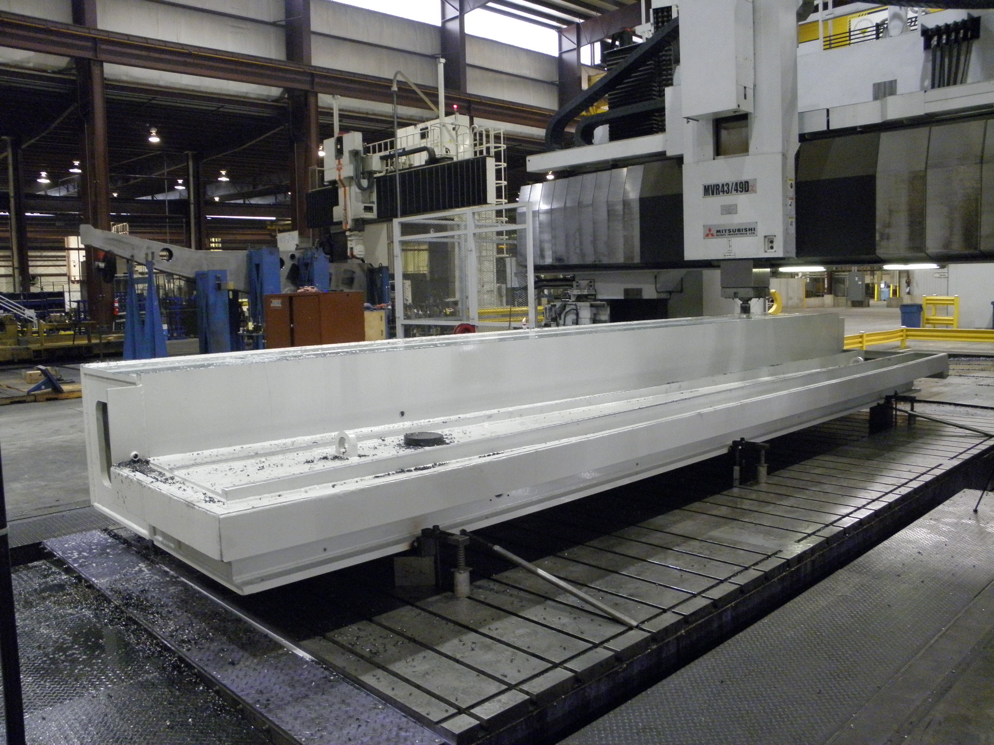
Figure 1 – Large Grinder Base Machining
Typical tolerances required on a base for a surface grinder that is 8.2 meters long are 0.0013 mm flatness and 0.0025 mm parallelism between surfaces. The combination of process planning, machine tool, tooling, machine operation and quality system delivers the tolerances expected by the grinder manufacturer. K&M has two Mitsubishi MVR43/49 Dx vertical gantry mills installed along with nine other large vertical gantry mills. K&M specializes in contract machining of large structures to tight tolerances. A video of a Mitsubishi MVR43/49 Dx vertical gantry mill machining a large grinder base can be seen below.
Figure 2 shows the large grinder base after machining and final paint.
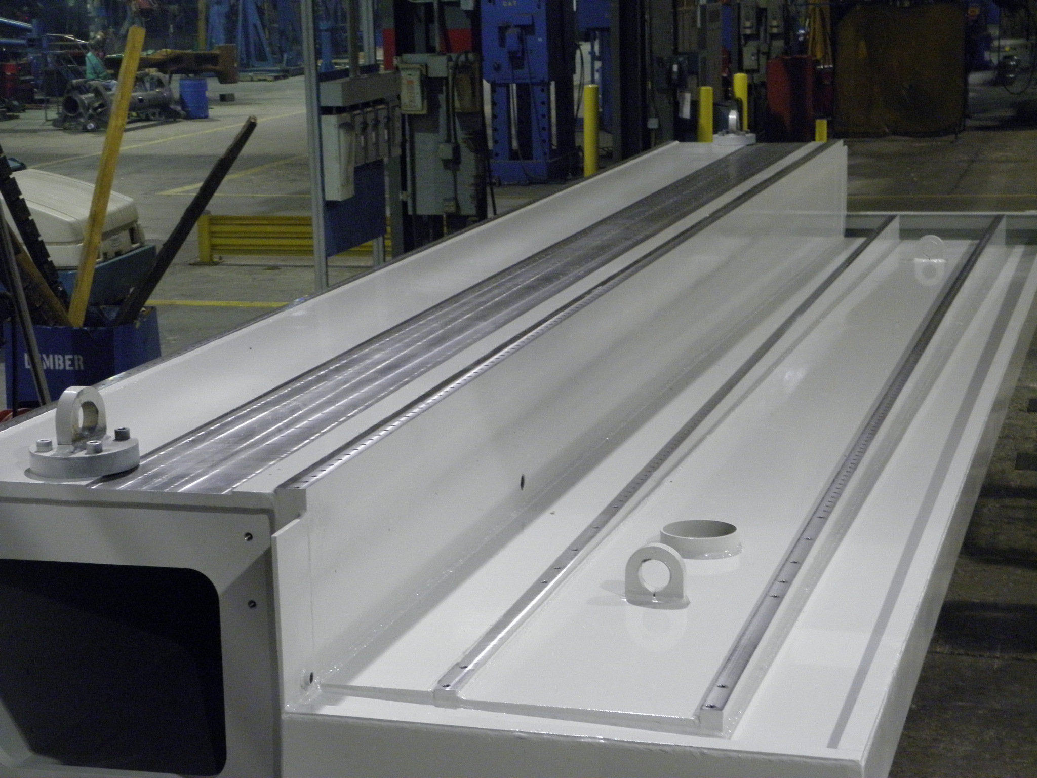
Figure 2 – Large Grinder Base after Machining and Paint
Back to the Large Machining Article Index
Large Machining of Weld Joint Surfaces for Large Fabrications
Many of the criteria for designing the weld joints for robotic welding apply to designing weld joints for manual welding in large fabrications. According to the American Welding Society weld joints must be repeatable for robotic welding to be successful. The same is true for welding large fabrications. The designer of large fabrications can chose to specify a machined weld joint or the designer can chose a cast weld joint surface on a casting or a plasma, oxyfuel, or laser cut weld joint surface on a plate burnout. Although a machined joint surface will increase the cost of a component, the savings in weld rework, rejection, and potential weld failure more than pays for the added cost. For large fabrications, large machining is required to produce the machined weld joint surfaces.
A large top level fabrication is typically made up of several smaller fabrications. These smaller fabrications can be 20 feet long with a fabrication tolerance of plus or minus 1/8 inch. When a fixture is used to locate these fabrications to each other the variation between the weld joint faces can vary plus or minus ¼ inch, or a range of ½ inch. A gap of less than zero is not allowed, so the gap can be as large as ½ inch. This is not a feasible condition for welding.
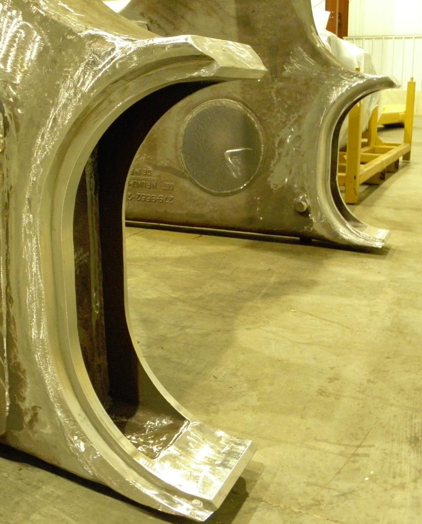
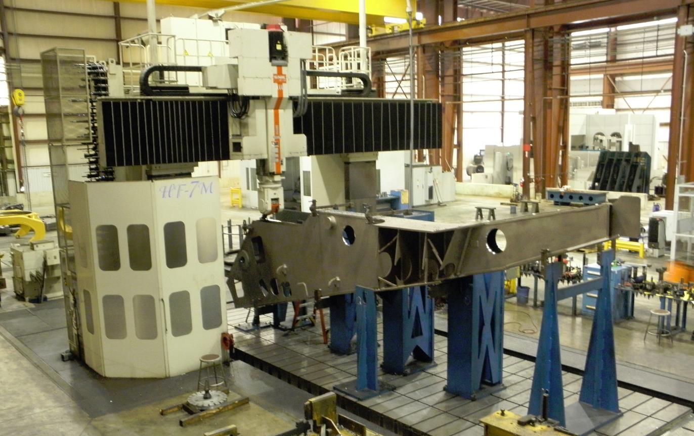
Robotic welding technology exists to overcome variation in the location of the welding joint. These technologies include touch sensing, through-the-arc tracking and vision systems. All of these systems are available proven technologies that are available for a cost. The one aspect of weld joint variation these systems do not overcome is the case of a large weld gap. The consequences of a large gap can be undersize welds, poor fusion, or inability to complete the weld. This translates into increased welding time, weld repair time, or poor quality welds. All of these consequences are costly. There is an alternative that greatly reduces the weld joint surface variation and eliminates the large weld gap. That alternative is to machine the weld joints on the large fabrication. Picture 1 shows a machined weld joint on a fabrication composed of two castings. Picture 2 shows a 20 foot long fabrication fixtured in a Large Vertical Gantry Mill for machining of all weld joint surfaces in a single setup.
Picture 1 – Machined Weld Joint
Picture 2 – Machine All Weld Joint Surfaces on 20 Foot Fabrication
The concept of using machined weld joints on large fabrications involves the specification of location and profile of the weld joint surfaces in relation to datums that are identified on the fabrication. These datums are used to locate the fabrication or casting for machining and the same datums are used to locate the fabrication or casting for final fit up and welding at the top level of the fabrication. Profile tolerances of plus or minus 0.002 inch are achievable with modern machining equipment. This will yield a variation of plus or minus 0.004 inches in the fit up of two weld joint surfaces. The potential gap is 0.008 inches. Compare this to the potential 0.5 inch gap on a joint that is not machined.
Weld joint surface designs may be at compound angles to the datums on the fabrication or casting. Machining equipment with right angle and/or universal heads will be required to produce the required weld joint geometry economically. This is done by machining all weld joints on a fabrication or casting in a single setup. The single setup also reduces the variation between weld joints on the same fabrication or casting.
K&M Machine-Fabricating Inc. has several large horizontal boring mills and large vertical gantry mills that are used to machine weld joint surfaces on large fabrications and large castings. View a video of large machining of weld joint surfaces below.
Back to the Large Machining Article Index
Visit K&M Machine-Fabricating, Inc. YouTube channel
Follow K&M Machine-Fabricating, Inc. on LinkedIn