Large Fabricating Articles
Contact Information
Sales Engineer
(269) 445-2495
Large Fabricating Article Index
- Estimating Large Fabrication Welding Costs
- Large Fabrication Welding
- Large Fabrication Submerged Arc Welding (SAW)
Estimating Large Fabrication Welding Costs
How do you estimate welding cost for a large fabrication? Estimating the weld hours at 100% welder efficiency is straight forward. The AWS Welding Handbook is a good resource. Difficulty arises when you must apply an efficiency factor to the welder. Welder efficiency can range from 5% to 100% depending on the weld process and fabrication size. Your best bet is to use historical data for your type and size of fabrications to determine a welder efficiency factor.
There is no “one size fits all”.
Back to the Large Fabricating Article Index
Large Fabrication Welding
Large fabrications are typically used as load bearing structures in critical applications. These applications include cranes on off-shore oil rigs, construction cranes, large gear boxes for underground and surface mining machines, frames for large (240 to 400 ton capacity) mining trucks, and sub-frames for engines for surface ships and submarines. Given the applications for these fabrications it is clear that structural integrity and dimensional accuracy are required. A failure in any of these applications is very costly. The fabrication process which includes cutting, beveling and forming of the steel plate, the tack operation, the welding process, stress relief, NDT (Non-Destructive Testing) and paint all contribute to the final quality of the large fabrication and must be controlled and the results verified.
For the purposes of this article a large fabrication is defined as a part that is 4 feet X 4 feet X 4 feet in size and that is fabricated from steel plate that is 3/8 inch and greater thickness. Steel plate in large fabrications is frequently up to 10 inches thick. Fillet welds in large fabrications typically range in size from 3/8 inch to 3 inch.
The steel grade is specified by the customer’s design engineer and is selected for its mechanical properties. Steel grade is a critical component of the performance of the large fabrication. High strength steel grades and low temperature grades are frequently specified. There are industry standard grades and customer specific steel grades. Certification that the steel plate meets the composition and mechanical properties of the grade as specified by the customer is supplied by the steel mill or through the intermediate steel distributor. Traceability of the steel grade and the material certification from the steel mill to the final product is required.
The selection of parameters for the welding process is influenced by the steel grade, weld joint configuration, application, and design tolerances. Process parameters include welding process (SAW, SMAW, GMAW, GTAW, FCAW), filler type, grade and size, wire feed speed, shielding gas, shielding gas flow rate, current and voltage. There are several industry standards for welding process parameters and other aspects of the welding process. For critical applications for welding of large fabrications customers will specify the particular industry standards that must be followed for the welding process. In many cases customers will have their own standards that supplement industry standards. Where no industry standard is specified by the customer the fabricator will typically follow standards given by the American Welding Society or an ISO welding standard.
The welding process parameters are defined in a PQR (Procedure Qualification Record) and WPS (Welding Procedure Specification). Sample plates are welded using the welding procedure defined in the PQR. The mechanical properties of the welds are tested by a certified testing lab. These tests and test results are certified as complying with the required standards by a CWI (Certified Welding Inspector). In some cases the customer or a customer defined third party must witness the welding and testing of the sample plates. The customer selected welding standard defines the range of welding parameters that are qualified by the PQR that was tested. The approved PQR is used to create the WPS. A CWI must approve the PQR and the WPS.
After the welding process is defined and approved the welders must be certified to weld using this process. The welder will weld sample plates using the approved WPS. These sample plates are inspected as required by industry or customer standards. The welder, once certified, must perform the welding operation at least every six months to maintain certification or she must retake the welding certification test for the welding process.
The welding process and the welder are now approved. Ongoing process controls must be used to insure that the approved process is used for every weld. These controls include:
- Calibration of the welding machines
- Verification of wire feed speed, voltage and amperage settings on the welding machines
- Verification of the use of proper welding technique by the welder through observation and audits
- Calibration of shielding gas mixture and flow meters
There are several types of inspection that can be done and that may be required by the customer. These include MT (magnetic particle testing), PT (penetrant testing), UT (ultrasonic testing) and load testing. These tests must be performed by certified inspectors and are subject to third party witness if required by the customer.
Dimensional control of large fabrications during the fabrication process is important. The customer will define the final dimensions and tolerances that are required on the finished fabrication. There are large heat inputs into the fabrication during the welding process and during the stress relief operation. These large heat inputs to the fabrication cause distortion. The manufacturing process designer must anticipate this distortion and take steps to minimize it or to compensate for it. Steps that can be taken include:
- Use of restraining bars to restrict distortion
- Sequencing of the welds to prevent distortion
- Pre-weld dimensions that compensate for anticipated distortion
- Blocking of the fabrication in the stress relief furnace
Welding is a critical process for the final quality of a steel fabrication. A great deal of scientific and engineering work has gone into the definition and standardization of welding processes and procedures. This work continues today and will continue into the future as new knowledge is discovered and new technology is applied. The steel fabricator must apply the current standards and stay up to date on advances in the field of welding to remain qualified to provide large steel fabrications and to remain competitive in this industry.
Back to the Large Fabricating Article Index
Large Fabrication Submerged Arc Welding (SAW)
Submerged arc welding is a proven processes with many benefits, including high productivity and high quality. It is particularly suited to welding on large fabrications in series production. There are a number of process steps that are important during the SAW welding process to insure that high quality welds are produced. K&M Machine-Fabricating Inc. uses the SAW process to weld large fabrications for series production.
Submerged arc welding was first used in the 1930’s. Today’s SAW equipment and processes are the result of many years of production use and improvements. Advantages of the SAW process are high deposition rates, deep weld penetration, and high productivity.
The SAW process is similar to the MIG (Metal Inert Gas welding). The SAW process uses a flux that is granular. The flux is used to generate shielding gases and slag and to add alloying elements to the weld pool. Picture # 1 shows the flux around the welding electrode.

Picture # 1 – Flux Deposited in Front of Welding Electrode
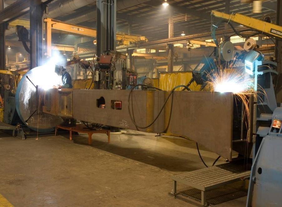
K&M Machine-Fabricating Inc. has two ESAB CaB300 Sub Arc machines. Each of these machines features a 3 meter column travel, 3 meter boom travel and they are mounted on a 50 foot long rail carriage. The size and travel of these machines are well suited for welding large fabrications. The machines are equipped with joint tracking and positioning capability. The welding heads are 1250 Amps. The Plasma gouging heads are 150 amp. The K&M Youtube channel features a video of the Subarc machine in action (link). This article will describe the Subarc process that is featured in the video. Picture # 2 below shows one of the subarc machines at K&M. The large fabrication that is in process is shown located to the right of the subarc machine.

Picture # 2 – Subarc Machine at K&M with Large Fabrication in Location
The weld demonstrated in the K&M video is typical of the welds produced using the subarc process at K&M. This joint is a 60 degree bevel. This weld joint requires 100% penetration and 100% UT inspection. Prior to positioning in the subarc machine a backing weld is applied to the weld joint on the large fabrication. Picture # 3 shows the weld joint prior to the plasma gouging and subarc welding that takes place on the subarc machine.

Picture # 3 – Weld Joint Prior to Plasma Gouging
The first step in the welding process for the large fabrication on the sub arc machine is to plasma gouge the joint. This process is required to insure that 100% penetration is achieved in the welding process. Picture # 4 shows the weld joint after plasma gouging.

Picture # 4 – Weld Joint After Plasma Gouging
After the plasma gouging operation the weld joint is ground with a grinding wheel to clean the joint and to achieve the proper weld joint geometry. The weld joint geometry is checked with a template gage. Picture # 5 shows the weld joint after grinding. The weld joint is also cleaned with a wire wheel.

Picture # 5 – Weld Joint After Grinding
A root pass is applied to the weld joint with the Flux Core (FCAW) welding process prior to welding with the sub arc machine and sub arc process. Picture # 6 shows the root pass in place in the weld joint.

Picture # 6 – Root Pass
The weld is cleaned with a chipping hammer and wire wheel after the root pass and between all SAW weld passes. After cleaning the first SAW pass is welded. Picture #7 shows the SAW welding in-process. The cooling molten slag can be seen to the right of the picture.

Picture # 7 – SAW Welding in Process
On a large fabrication the size of the weld joint will often require multiple SAW passes. Interpass cleaning and inspection is a critical part of the welding process. Any irregularities must be found between passes. Finding indications after all passes are complete will require repair of the weld joint. Repair costs will detract from the cost savings that were achieved by using the SAW process. Picture # 8 shows multiple passes and cap passes.

Picture # 8 – Multiple SAW Passes
The SAW process produces a weld that is visually appealing. Not only is it a high quality weld (these welds are 100% UT inspected), it looks like a high quality weld. PICTURE #9 shows the finished weld after the cap passes are complete. K&M’s customers, their customers, and the user in the field appreciate the high quality and good visual appearance of the SAW welds.

Picture #9 – Cap Passes
The SAW process is one of the many welding processes that K&M uses to manufacture large fabrications. The same focus on welding processes and quality that is used in the SAW process is used in all of K&M welding processes.
Back to the Large Fabricating Article Index