K&M Machine-Fabricating Inc. specializes in the machining of large fabrications and large castings. Our precision machine shop includes 37 CNC machines. 10 large vertical gantry mills and 19 large horizontal boring mills are on line at K&M to meet your large part machining needs. These machines are equipped with a variety of right angle heads, universal heads, spindle extensions and probes to insure that your large machining needs for accuracy, precision and on time delivery are met.
Our equipment list will give you a complete list of all the CNC machines that are installed at K&M. The information in this section of the web site will give you more in depth information on specific machines at K&M. The in depth information on machines will be updated periodically by adding information on additional machines that are in operation at K&M.
Large CNC Machine Index
Vertical Gantry Mills (Largest to Smallest)
Horizontal Boring Mills (Largest to Smallest)
Horizontal Machining Centers (Largest to Smallest)
Large Machining Article Index
- Large Machining Simulation
- Large Machining Capacity Strategy to Meet Changes in Demand
- Large Machining of Base Fabrication for Machine Tools
- Large Machining of Weld Joint Surfaces for Large Fabrications
- Large CNC 3+2 Machining, Lean Manufacturing and the Seven Forms of Waste
- High Feed Milling Large Steel Castings – Don’t Let Casting Inclusions Disrupt Your Supply Chain
- Large CNC Machining Of Steel Casting – Custom Head for Tight Clearance Milling
- Process Controls for Contract Manufacturers of Large Machining and Large Fabrications – Part One – Customer Supplier Interface
- Large Machining of Large Bores – Machining, Measurement, Data Collection, Traceability and Data Retention
- How Large Is Large? Survey of Large CNC Machining In Michigan
K&M Machines #121 and #124 – Mitsubishi MVR 43/49 Dx Vertical Gantry Mills
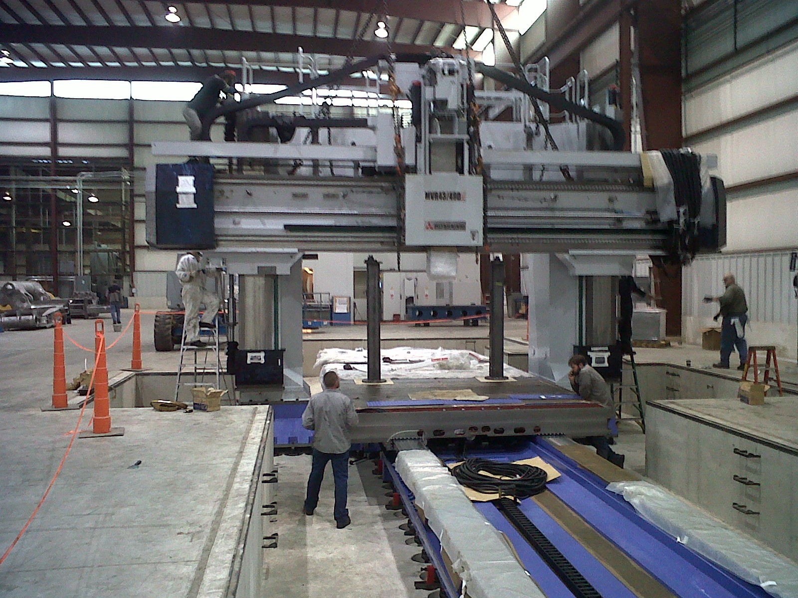
K&M has two Mitsubishi MVR 43/49 Dx Vertical Gantry Mills installed and operational. These machines are the largest vertical gantry mills that Mitsubishi has installed in North America as of 10/21/14. Table 1 lists the capacities of Machines #121 and #124. Table 2 lists the attachments installed on the machines. Machine #121 is shown in Picture 1 below.
| Pallet Size | 3,500 MM X 8,000 MM |
| X Axis Travel | 9,000 MM |
| Y Axis Travel | 4,900 MM |
| Z Axis Column Travel | 2,200 MM |
| W Axis Spindle Travel | 1,000 MM |
| Spindle Housing | 400 MM X 400 MM |
| Tool Changer Capacity | 80 Tools |
| Maximum Weight Work Piece | 123,400 LBS |
| Maximum Spindle Speed | 4,000 RPM |
Table 1 – Machine #121 and Machine #124 Capabilities
| Large Right Angle Head |
| Small Right Angle Head |
| Universal Head |
| Spindle Extension |
| Probe |
Table 2 – Machine #121 and Machine #124 Attachments

Picture 1 – Machine #121
Machine #124 is identical to M#121 shown above. It was installed one year after Machine #121.
FOUNDATION
The preparation of the foundation and installation are an important aspect of the quality, efficiency and safety that are delivered by these machines. The concrete foundations for these two machines are 8 feet thick and are composed of approximately 600 yards of concrete. The soil at K&M is a clay gravel mix. If the soil was a sandy composition the foundation would have to be 20 feet thick. The concrete cools from an initial temperature of 190 degrees F to 90 degrees F over a period of approximately 28 days during the curing process. A temperature probe is embedded in the concrete to determine when the cure temperature has been reached. The foundation for Machine #124 under construction is shown in Picture 2. The final foundation for Machine #121 is shown in Picture 3.
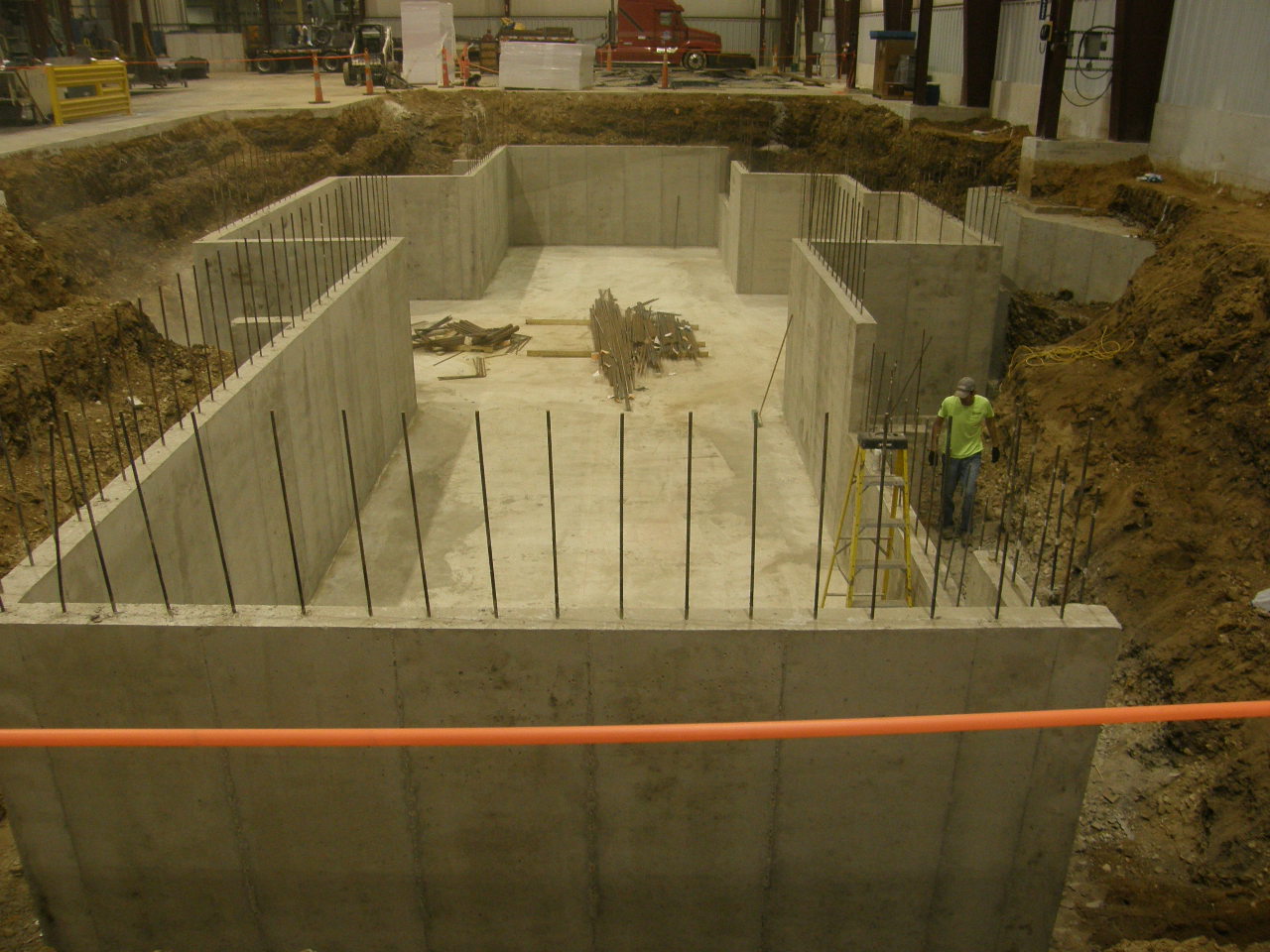
Picture 2 – Machine #124 Foundation Under Construction
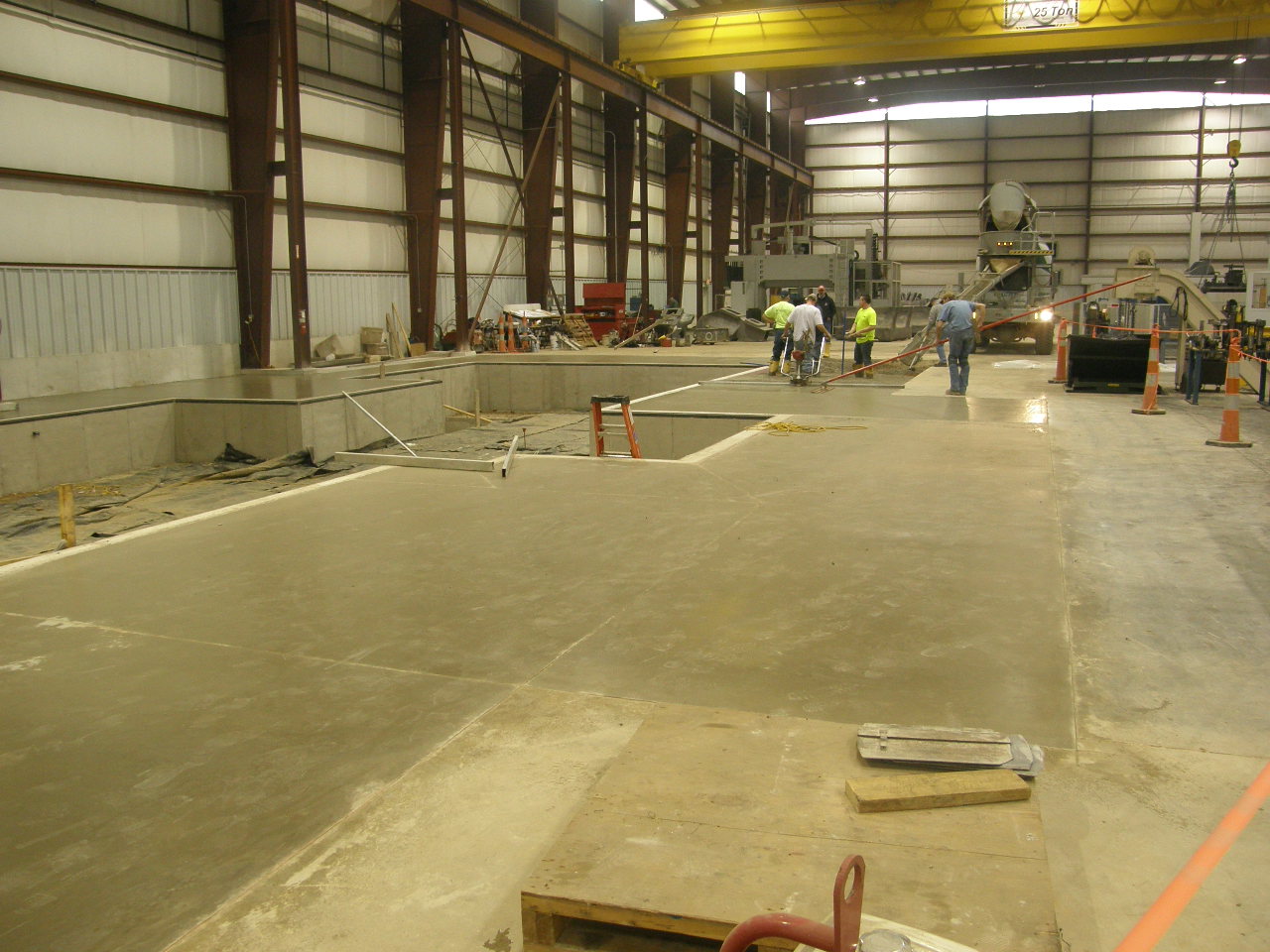
Picture 3 – Machine #121 Foundation Complete
The table height as shown in Picture 1 is at floor level. This makes loading and unloading large work pieces easier and safer for the machine operator. This increases machine efficiency and lowers operating costs.
CAST IRON STRUCTURE
The Mitsubishi MVR 43/49 Dx Vertical Gantry Mills are constructed for rigidity and powerful milling. The machine main structure is cast iron and was designed using FEA (finite element analysis) to locate the main casting rib in the optimum position to achieve high rigidity. This main structure contributes to the high accuracy produced by the milling machine and the high stock removal rates that can be achieved.
SPINDLE
The square ram is constructed of high tensile cast iron. It is 400 mm square. This construction enables the application of the full spindle power of 45 kW at the full 800 mm extension of the ram. The powerful spindle motor output of 45kW is at the top level for this class of machine tool. 2,793 N-m of torque can be achieved at a spindle speed of 4,000 RPM. Full power milling can be achieved at the low spindle speed of 154 RPM. The main spindle is driven by two step helical gears. This drive system has low noise, minimum backlash and contributes to high rigidity.
SLIDE WAYS
The dual vertical slide ways for cross rail up and down movement are mounted on the front face of the columns. They are wide to enable full power milling at any position of the saddle on the cross rail. The X axis slide ways use hydro-static guides to obtain stable feed under heavy loads. The Y axis slide ways are high rigidity roller type linear guides to assure accurate positioning of the saddle. The Z and W axes are sliding guides with high-level damping performance and automatic intermittent lubrication. The crossrail is balanced with two counter weights. See Picture 4 for a view of the slide ways.
Picture 4 – Guide Ways
CONTROL
Machines #121 and #124 are equipped with FANUC Series 31i CNC controls. The control is equipped with macro programs for the attachments and for work surface coordinate programming which allows programming on an inclined face as a X-Y surface. There are also macros for machining patterns. The powerful control facilitates rapid generation of complex part programs and ease of operator and programmer interface with the machine. Picture 5 shows the CNC control.
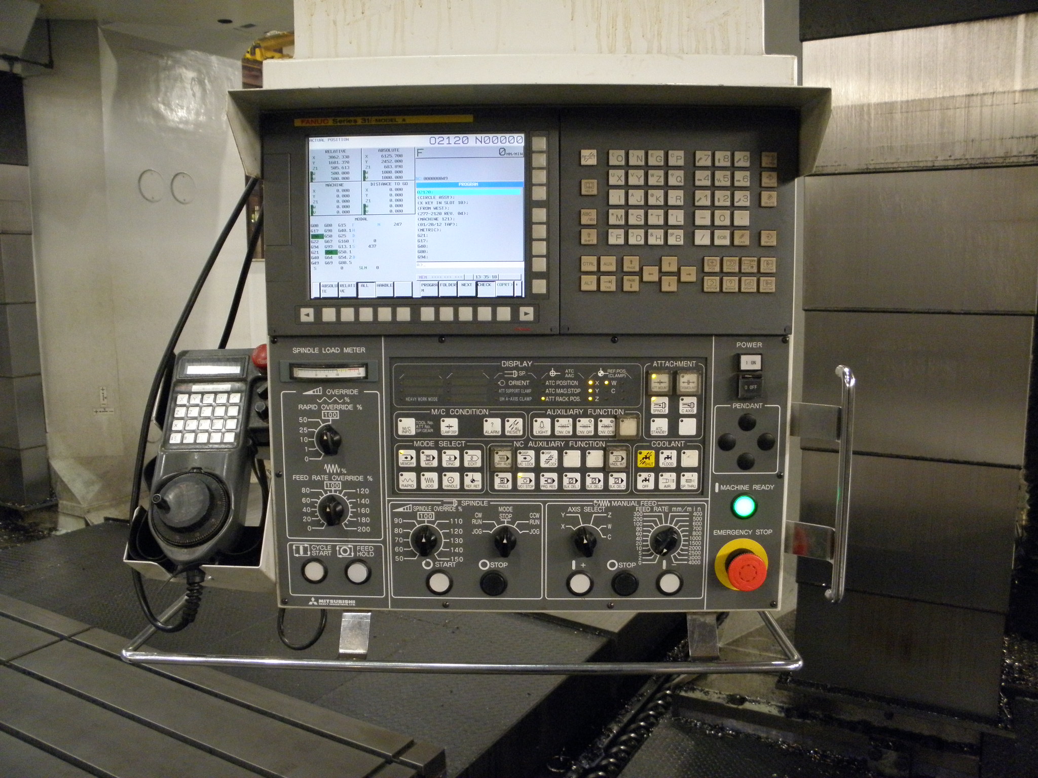
Picture 5 – Fanuc Series 31i Control
ATTACHMENTS
The attachments on Machine 121 and Machine #124 include a small right angle head and a large right angle head. The small head allows machining in tight locations while the large head allows for heavy metal removal. There is also a universal head for machining at an angle and a spindle extension. The spindle extension allows machining at a long reach, past obstacles on the work piece.
SUMMARY
The two Mitsubishi MVR 43/49 Dx Vertical Gantry Mills installed at K&M are built for multisided large machining. They are built for high stock removal and accuracy. These two machines along with several other large vertical gantry mills installed at K&M give our customers redundant capacity and available capacity to meet immediate machining requirements. The construction, installation and options on these machines give one of the best combinations of productivity and accuracy that is available for large machining needs. Customers of K&M can take advantage of this large investment in modern large machining capacity without the capital investment and ongoing costs of ownership. Fixed machine costs become a variable cost when the machining service is purchased from K&M. A video of Machine #124 may be viewed below.
Back to the Large CNC Machine Index
K&M Machine #111 – SNK HF-7VM Vertical Gantry Mill
K&M has 11 large CNC vertical gantry mills. Six of these CNC vertical gantry mills were built by SNK. The largest of the SNK CNC vertical gantry mills owned by K&M is an SNK HF-7VM. Table 1 lists the capacities of Machine #111. Table 2 lists the attachments installed on Machine #111. Machine #111 is shown in Picture #1 below.
| Pallet Size | 3,500 MM X 10,000 MM |
| X Axis Travel | 11,000 MM |
| Y Axis Travel | 4,700 MM |
| Z Axis Column Travel | 2,450 MM |
| W Axis Spindle Travel | 1,000 MM |
| Spindle Housing | 500 MM X 500 MM |
| Tool Changer Capacity | 90 Tools |
| Maximum Weight Work Piece | 132,000 LBS |
| Maximum Spindle Speed | 3,000 RPM |
Table 1 – Machine #111 Capabilities
| Right Angle Head |
| Universal Head |
| Spindle Extension |
| Probe |
Table 2 – Machine #111 Attachments
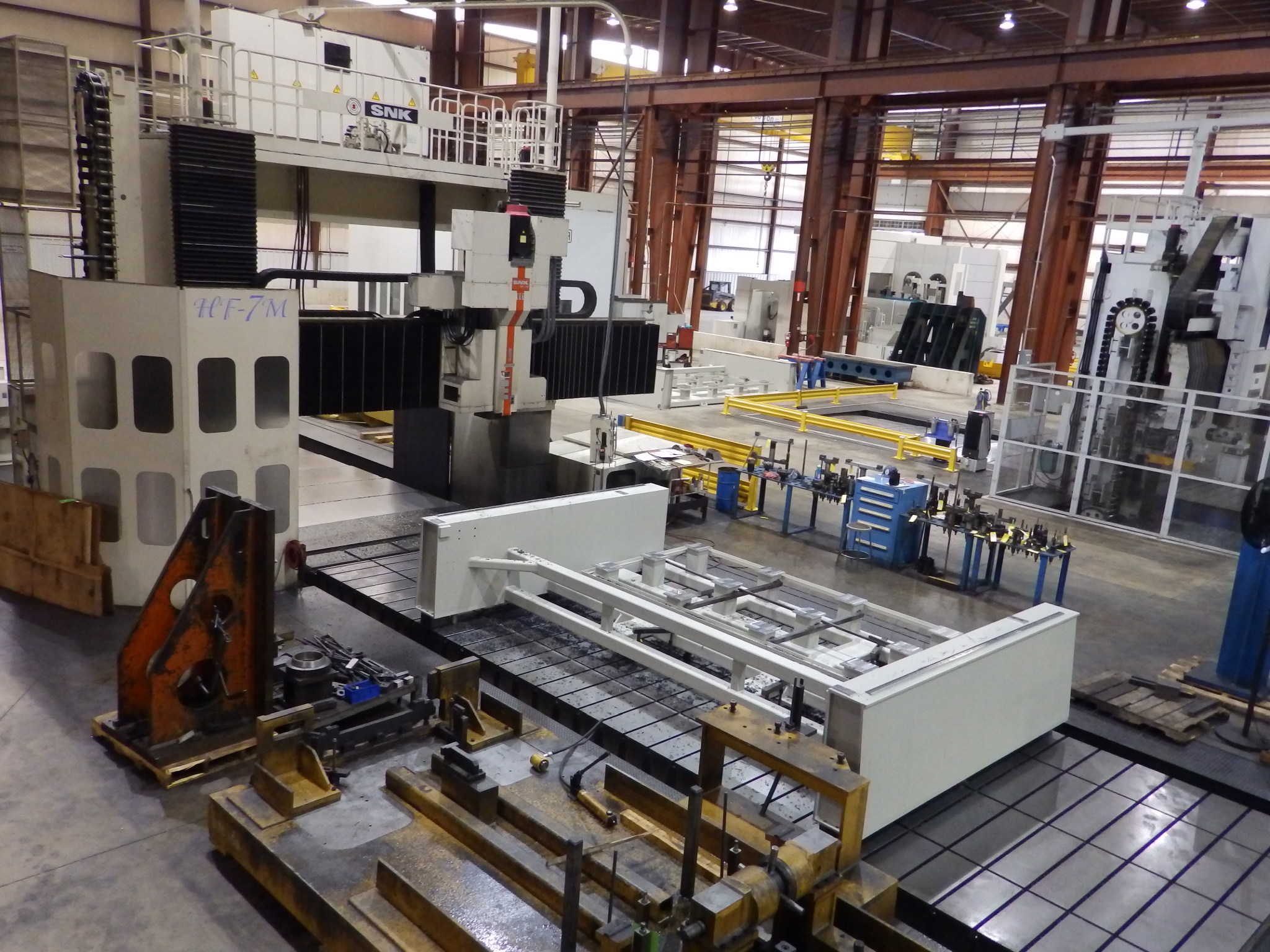
Picture #1 – Machine #111
Machine #111 is constructed for precision machining and rapid metal removal on large work pieces. It is a fast and heavy duty machine. There are many features of the machine which contribute to its precision. Temperature controlled lubricating oil is used throughout the machine. There are temperature control systems for the spindle bearings and the attachment bearings.
The cross rail is moved up and down by two ball screws, one on each column. These ball screws are hydrostatically lubricated. Each column is equipped with hydraulic cylinders that act to maintain balance of the cross rail as the spindle head moves on the cross rail in the horizontal direction.
The table is supported by a hydrostatic slideway. The slideway provides pressure in both the horizontal directions and the vertical direction.
Machine #111 is equipped with many software macros that enhance operator and programmer productivity. 5 sided or 3+2 machining is a feature of this machine. The attachments are loaded and unloaded under program control. The automatic tool changer is capable of loading and unloading tools to all the attachments under program control.
The size and rigidity of Machine #111 along with the attachments and software make this a flexible and productive machine for machining large work pieces. The ability to reach five sides of a part in one set up and to machine hard to reach areas at compound angles to the table means that many parts can be machined in one setup. This translates into a higher quality finished product. Any time a part is setup multiple times variation is introduced. One setup reduces variation and improves quality.
Picture # 2 shows the universal head in action. Picture # 3 shows the right angle head in action.
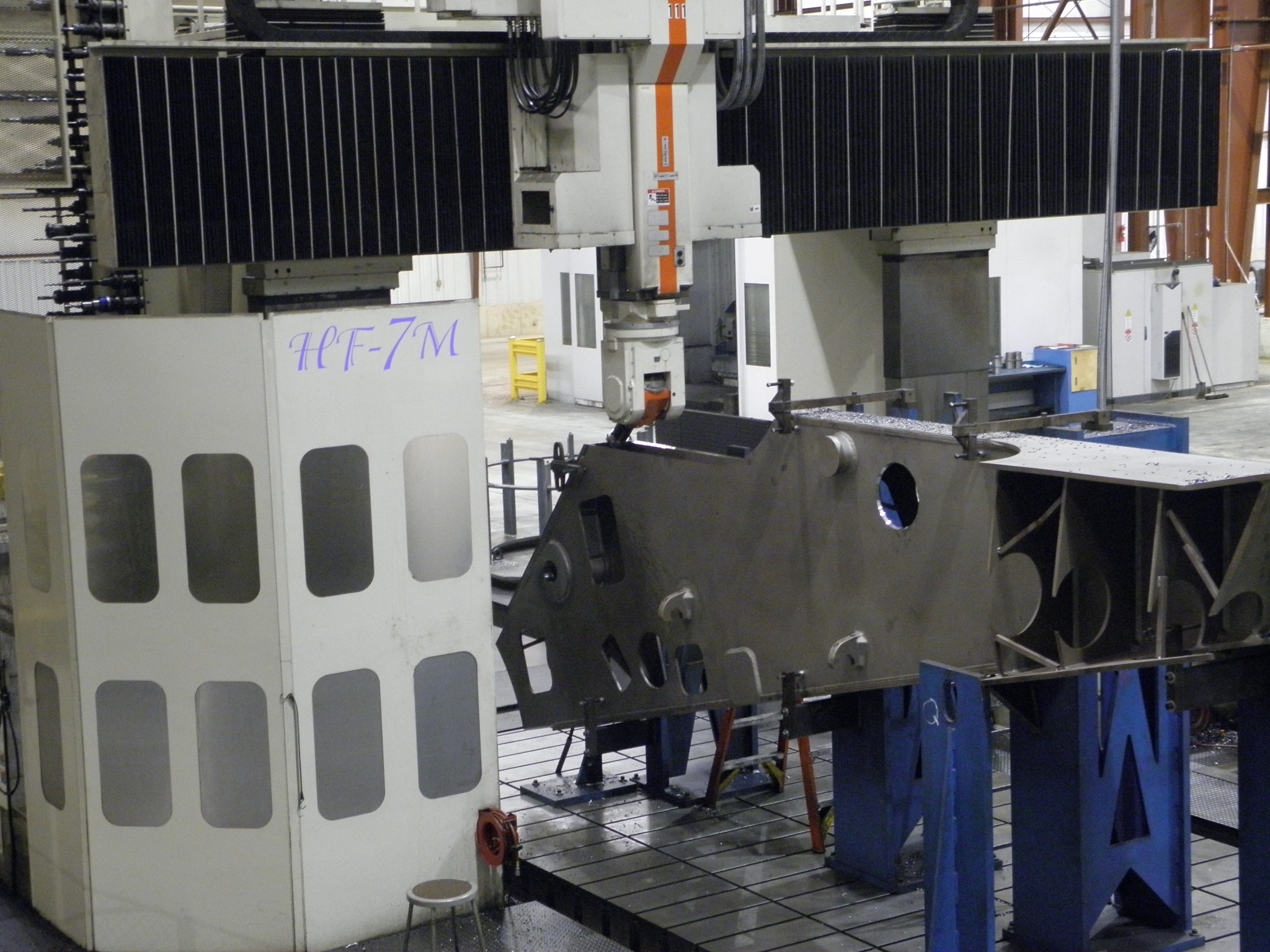
Picture 2 – Universal head on Machine #111
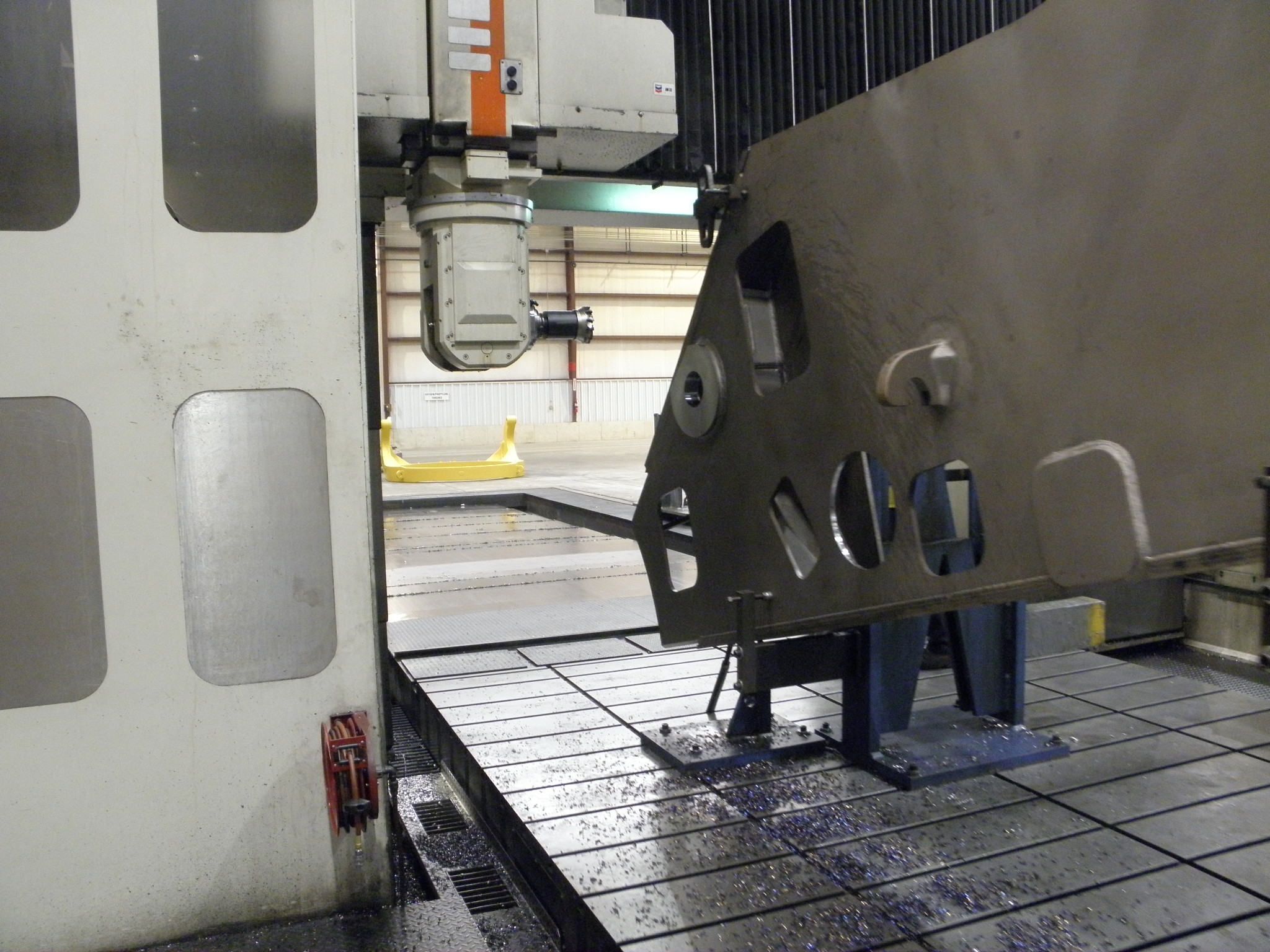
Picture 3 – Right angle head on Machine #111
Back to the Large CNC Machine Index
K&M Machine #125 Mitsubishi MAF-180C Horizontal Boring Mill
K&M Machine-Fabricating Inc.’s Machine #125 is a large CNC horizontal boring mill ideal for large machining work. It is a Mitsubishi MAf-180C, capable of handling a part 12 meters long, 5 meters high and 4 meters wide weighing up to 132,000 pounds. An important feature of this machine is the ram and spindle extension which give the machine a reach of 2,250 mm (88 inches). Large machining often requires a long reach into the work piece for machining of critical characteristics. Machine #125 can do the job. Picture 1 shows the ram and spindle partially extended during a plunge milling operation. Picture 2 shows the ram and spindle extended with the spindle reaching through one bore to machine the interior bore. Table 1 lists the capacities of Machine #125. Table 2 lists the features that are installed. Picture 3 shows Machine #125. The following video is a demonstration of the capabilities of Machine # 125.
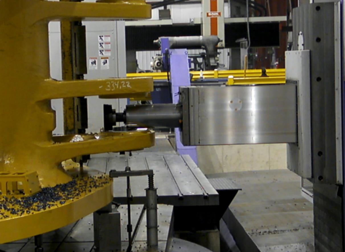
Picture 1 – Ram And Spindle Partially Extended. Plunge Milling.
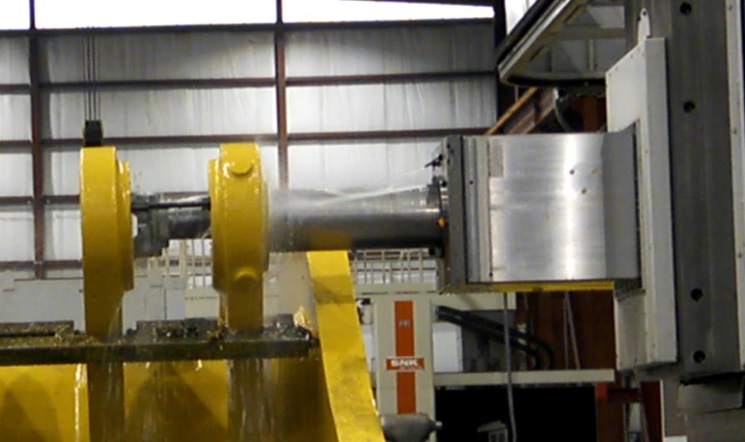
Picture 2 – Ram And Spindle Extended. Boring.
| Pallet #1 | 4,000 MM X 4,000 MM |
| Pallet #2 | 4,000 MM X 4,000 MM |
| Rotary Table | 3,000 MM X 3,500 MM |
| X Axis Travel | 20,000 MM |
| Y Axis Travel | 5,000 MM |
| Z Axis (Ram) Travel | 1,250 MM |
| W Axis (Boring Spindle) Travel | 1,000 MM |
| Ram Size | 400 MM X 420 MM |
| Spindle Diameter | 180 MM |
| Tool Changer Capacity | 80 Tools |
| Maximum Weight Work Piece | 132,000 LBS |
| Maximum Spindle Speed | 2,500 RPM |
Table 1 – Machine #125 Capabilities
| Right Angle Head |
| Universal Head |
| Probe |
| Rotary Table |
Table 2 – Machine #125 Features

Picture 3 – Machine #125
STRUCTURE
All of the main structures of the MAF-180C are castings that were designed using FEA (Finite Element Analysis) to deliver high rigidity, stability and accuracy under all machining conditions. The material grade of the casting used for the 420 mm square ram was chosen for its vibration dampening effect which yields excellent machining capability even when the ram is fully extended. This construction contributes to the high productivity during high metal removal rate machining.
SPINDLE AND DRIVE
The 180 mm diameter spindle has a maximum speed of 2,500 RPM. This spindle speed, combined with the maximum 8 meter/minute feed rate allow the use of high feed milling and high metal removal rates. Maximum power cutting can be achieved at a spindle speed as low as 101 RPM. A multistep helical gear system is used which provides quiet operation and minimal backlash. It is a very rigid design. Maximum spindle power is 85 kW (201 HP). Maximum torque is 8,000 N-m (5,900 ft-lb). Productive and precise deep narrow boring of a work piece is possible with the combination of ram travel, spindle travel, spindle diameter, and spindle motor.
SLIDE WAYS
Box type hydrostatic slide ways are used on the X and Y axes which deliver a smooth feed motion under high load. The column and bed design combined with the hydrostatic slide ways result in the ability to utilize high horsepower machining even when the spindle is located at the highest column position. Large machining means large work pieces. The spindle will frequently be located at a high column position. Productivity and accuracy are required at this position.
FEED MOTORS AND DRIVE SYSTEM
Rapid traverse rates as high as 10 meters/minute are possible further increasing productivity by reducing air-cut time. Large diameter preloaded ball screws on all feed axes delivery zero backlash which results in high accuracy and precision in positioning. In large machining the machining operations are often spaced far apart on the work piece. The time for the machine to travel between the work areas can be a significant contributor to total cycle time. The high rapid traverse rates contribute to productivity and cost reduction.
THERMAL EFFECTS ON MACHINING
Thermal expansion on large steel work pieces must be taken into consideration in large machining. The MAF-180C is designed to minimize the effect of temperature from the environment and the machine tool. A number of active and passive cooling systems are employed.
CONTROL
The control on Machine #125 is a Fanuc Series 31i CNC control.
SUMMARY
Machine #125 installed at K&M is a highly productive and accurate machine ideally suited for your large machining work. It is serviced by two 50 ton cranes.
Back to the Large CNC Machine Index
K&M Machine #126 – PAMA SPEEDMAT 4-160 Horizontal Machining Center
Machine #126, PAMA SPEEDMAT 4-160 is the largest of K&M’s five large horizontal machining centers. In was installed new in 2013 and is equipped to efficiently perform large casting and large fabrication machining. This machine is equipped with two automatic pallet changers, which reduce machine downtime for load and unload operations. The pallets are each 2.0 X 2.5 meters. The X axis travel is 3.8 meters and the Y axis travel is 3.0 meters. The column travels to achieve 2.6 meters of Z axis motion. In addition the quill has 0.8 meters of travel for a total of 3.4 meters of travel in along the Z axis. This machine can handle a part that weighs up to 44,000 pounds.
The SPEEDMAT 4-160 at K&M is equipped with a right angle head that is loaded and unloaded under CNC program control and is positioned under CNC program control. This machine has an automatic tool changer with a 120 tool capacity. The control is a Siemens 840D. Picture #1 shows the front of the Machine #126 and the two automatic pallet changers. Picture #2 shows the side of the machine. The operator station to load tools to the tool changer is at the left of Picture # 2. Safety interlocks allow access to the tool magazine only when motion has been locked out. The chip conveyor system is visible in Picture # 2. Two chip conveyors remove chips from the machine enclosure and deposit them to a single chip conveyor which feeds the chip hopper.
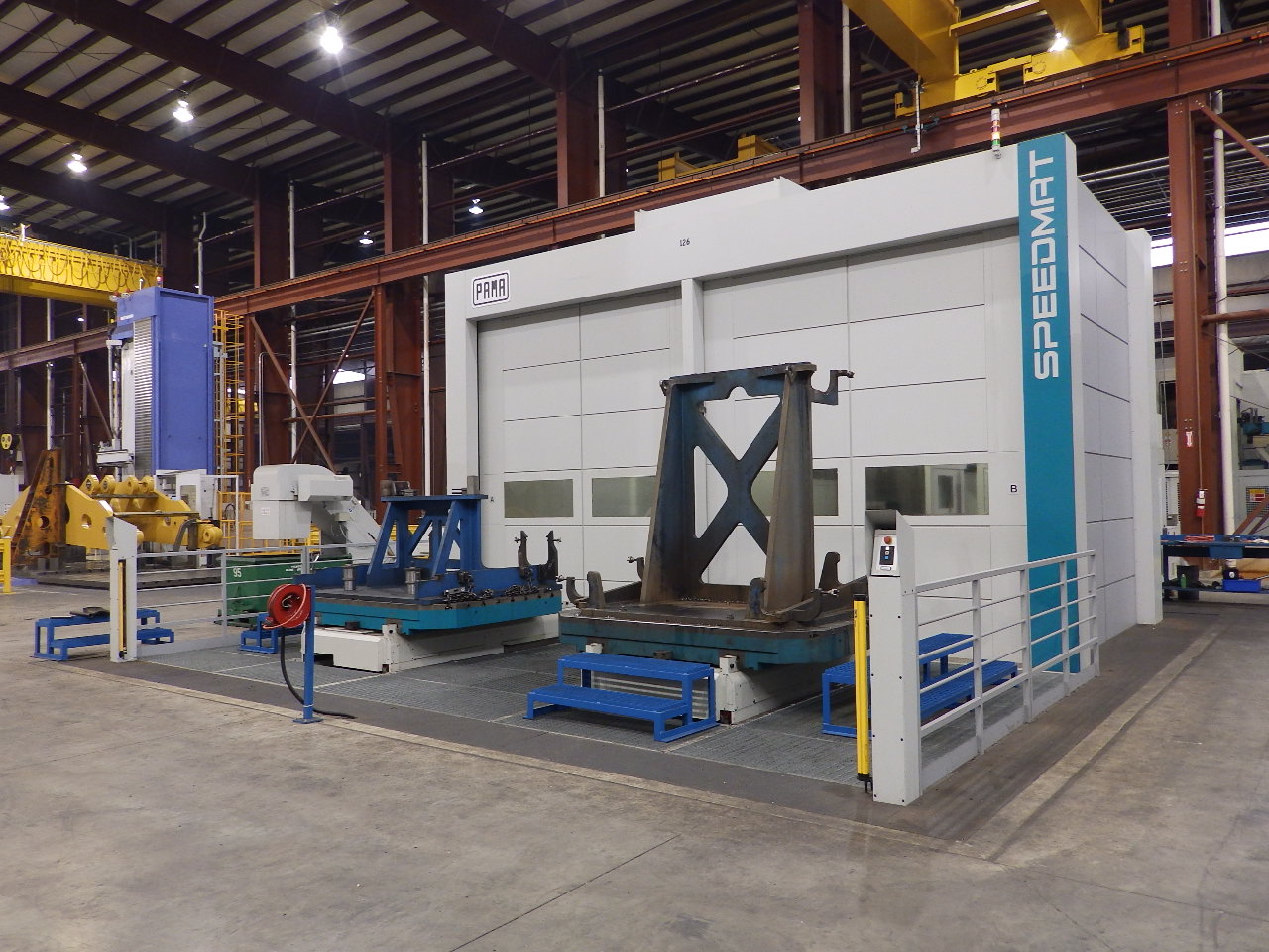 Picture #1 – Two Automatic Pallet Changers |
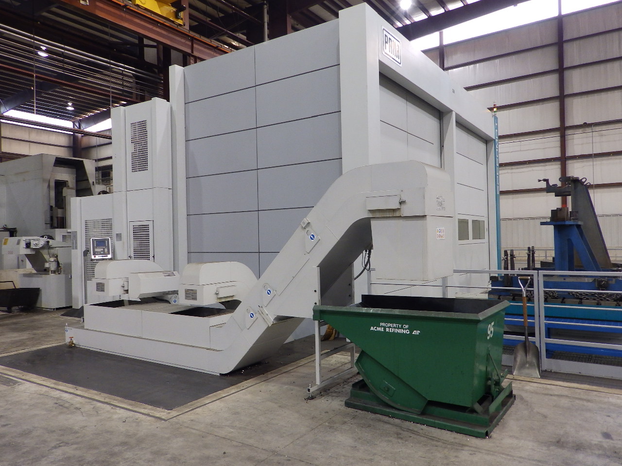 Picture #2 – Tool Magazine Load Station and Chip Conveyors |
Picture # 3 shows the 120 tool capacity tool magazine. Picture # 4 shows the operator control station for the Siemens 840D control.
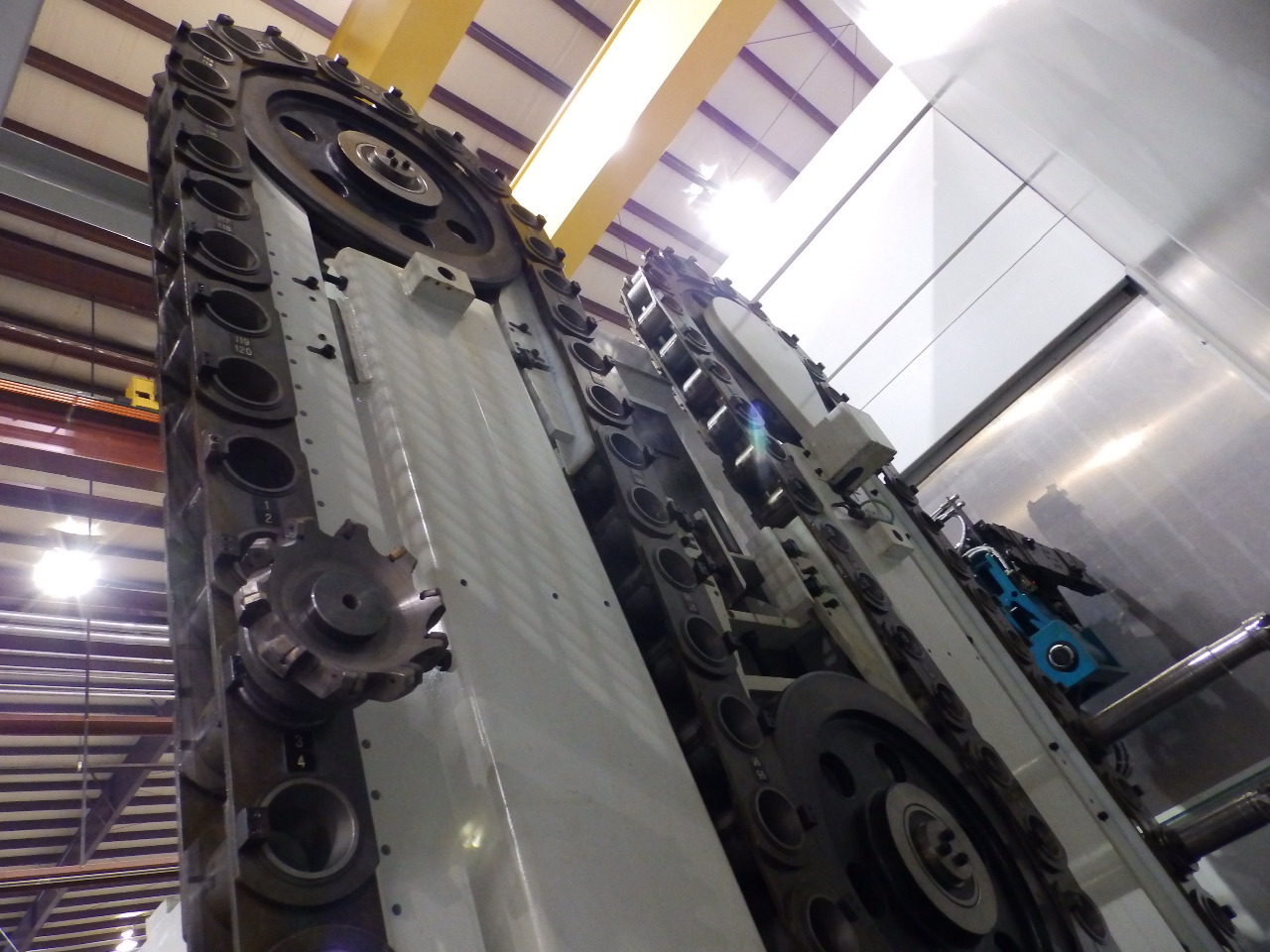 Picture #3 – Tool Magazine |
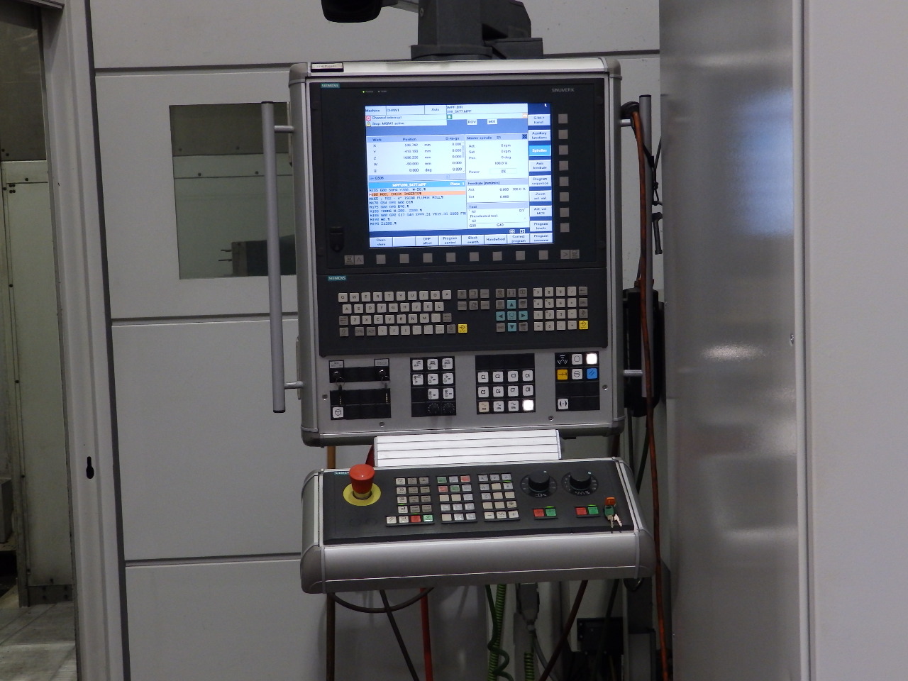 Picture #4 – Siemens 840D control |
Movement of the all linear axes are supported and guided by linear roller bearing guides with automatic lubrication. Linear optical transducers are used to control motion on all axes. The linear roller bearing guides are designed for rapid movement. The linear optical transducers insure accurate positioning.
The right angle head is automatically clamped and connected to the front of the machine head. Tools are automatically loaded to the right angle head. The right angle head is rotated around the C axis by rotation of the machine spindle and is held in place with Hirth couplings. An incremental optical transducer is used to read movement and position around the C axis.
Machine #126 has both high pressure and low pressure through the spindle coolant. The spindle gear box is equipped with a continuously recirculating lubrication system that is temperature controlled. The spindle bearings are equipped with multiple temperature sensors. There is also a temperature sensor in the spindle that monitors the ambient temperature. These temperature sensors are used to stop spindle rotation when there is danger of spindle damage. The work area is completely enclosed. All chips, coolant and tooling are contained in the work enclosure. Noise is also contained. The work enclosure improves plant health and safety.
The spindle motor power is 70 HP. Maximum spindle rotation speed is 2,000 RPM. Spindle diameter is 160 mm.
The Siemens 840D control is operator and programmer friendly. There are many macros available in the control and it has an adaptive control function. Adaptive control varies the feed rate to maintain a constant spindle power load.
Machine #126 is designed for automatic production machining of large components. The automatic pallet changers, automatic head changer, automatic tool changer with 120 tool capacity, and work enclosure allow production machining to continue uninterrupted. The two pallets can be loaded with different parts to be machined. The machine recognizes the pallet and loads the correct CNC program for the part. Loading and unloading of the fixtures is done by the operator outside of the work enclosure while machining of the part on the other pallet is taking place.
The machine is designed for speed and accuracy. The linear guide ways enable fast motion, the optical transducers insure accuracy. Power is not sacrificed. The 70 HP spindle motor allows high stock removal rates.
Machine #126 is an ideal machine for sub contract machining of large components. You can see a video of Machine #126 below.